
Touch panel

A touch panel and flat technology, which is applied in the fields of instruments, computing, electrical and digital data processing, etc., can solve problems such as errors in the location of the touch, misjudgment of the location of the touch by the control circuit, and increase in the production cost of the touch panel.

Inactive Publication Date: 2014-01-01
MSTAR SOFTWARE R&D (SHENZHEN) LTD +1
View PDF4 Cites 1 Cited by
  • Summary
  • Abstract
  • Description
  • Claims
  • Application Information

AI Technical Summary

Problems solved by technology

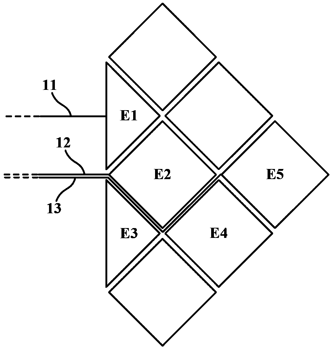
Since the connection lines passing through the narrow gap often need to use a photomask, the production cost of the touch panel will increase significantly
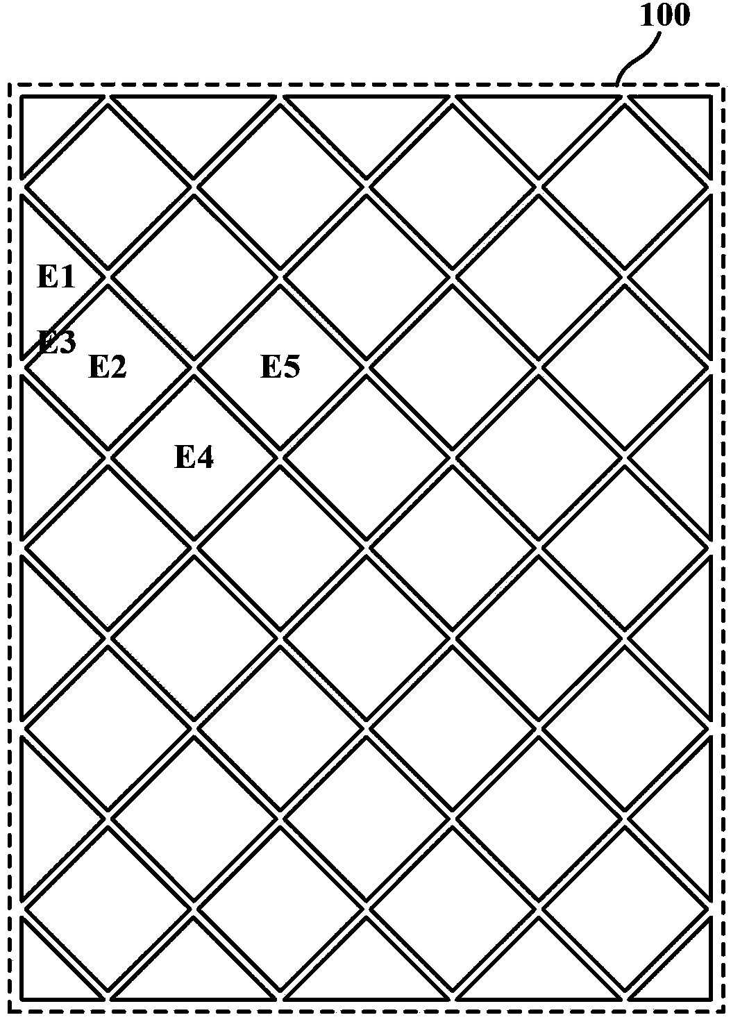
[0006] On the other hand, since the material of the connection wire is usually metal that is also affected by the user's touch, the connection wire passing through the gap may cause the control circuit to misjudge the location of the touch
For example, if the user touches between the electrodes E2 and E4, the connecting wire 13 passing through the gap between the electrodes E2 and E4 will also be affected, thereby causing the sensor connected to the electrode E5 to detect a change in capacitance
When the detection results of the sensor connected to the electrode E5 are also taken into consideration, the position of the touch determined by the control circuit will obviously have an error

Method used


Image

  • Touch panel
  • Touch panel
  • Touch panel

Examples


Embodiment Construction

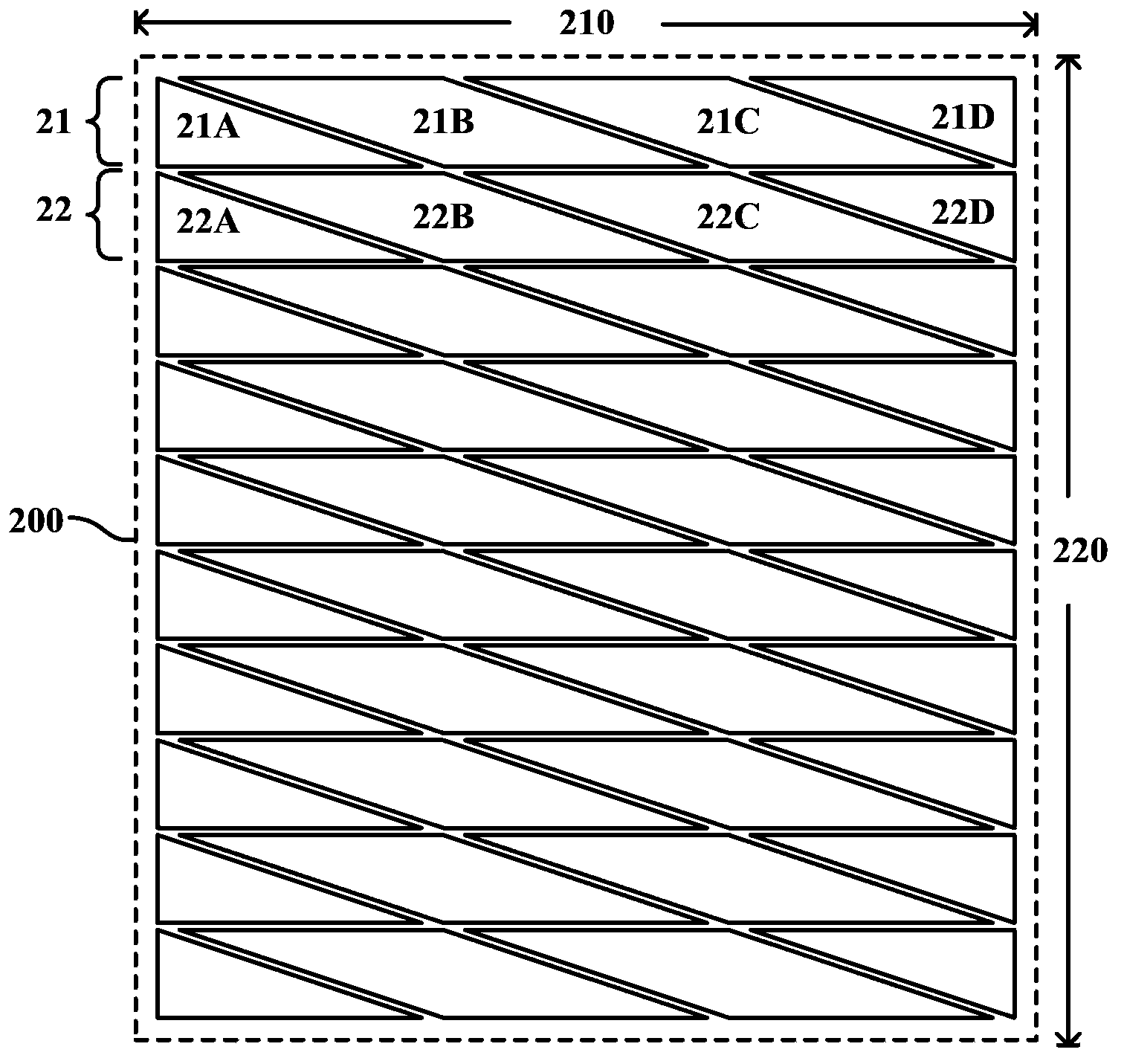
[0024] An embodiment according to the present invention is a touch panel, wherein the electrode shape / configuration is as follows Figure 2A shown. Multiple rows of electrodes on the same plane constitute the sensing region 200 . Each column of electrodes in this embodiment includes two parallelogram electrodes and two right triangle electrodes respectively. Taking the first row of electrodes 21 at the top of the screen as an example, it includes a right triangle electrode 21A, a parallelogram electrode 21B, a parallelogram electrode 21C, and a right triangle electrode 21D from left to right.

[0025] Depend on Figure 2A It can be seen that the sensing region 200 has a first boundary 210 and a second boundary 220 that are substantially perpendicular to each other. The parallelogram electrodes 21B, 21C each have two sides parallel to the first boundary 210 , and the other two sides of the parallelogram electrodes 21B, 21C are not parallel to the first boundary 210 nor paral...


PUM


Abstract

A touch panel including plural electrodes is provided. The plural electrodes form a sensing region and are disposed on the same plane. The sensing region has a first border and a second border substantially perpendicular to each other. The electrodes include one parallelogram electrode. The parallelogram electrode has two first edges parallel to the first border and two second edges parallel to neither the first border nor the second border.

Description

technical field [0001] The present invention is related to a touch system, and in particular to a technique for improving the accuracy of a sensing result in an edge area of ​​a touch panel. Background technique [0002] With the advancement of technology, the operation interfaces of various electronic products have become more and more user-friendly in recent years. For example, through a touch screen, users can directly operate programs and input messages / texts / patterns on the screen with fingers or a stylus, saving the trouble of using input devices such as keyboards or keys. In fact, the touch screen usually consists of a sensing panel and a display disposed behind the sensing panel. The electronic device judges the meaning of the touch according to the position touched by the user on the sensing panel and the picture displayed on the display at that time, and executes the corresponding operation result. [0003] Existing capacitive touch technologies can be classified...

Claims


Application Information

Patent Timeline
IPC IPC(8): G06F3/044
Inventor 刘峻诚蔡孟哲许得卫
Owner MSTAR SOFTWARE R&D (SHENZHEN) LTD
Learn More