Pixel circuit, driving method thereof, array substrate and display device
A technology of pixel circuit and driving method, which is applied in the field of display driving, can solve the problems of short life, lower AMOELD, and low luminous efficiency of blue OLED, and achieve the effect of improving life and prolonging use time
- Summary
- Abstract
- Description
- Claims
- Application Information
AI Technical Summary
Problems solved by technology
Method used
Image

Examples
no. 1 example
[0104] Such as Figure 7 As shown, the first embodiment of the pixel circuit driving method of the present invention includes:
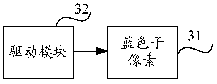
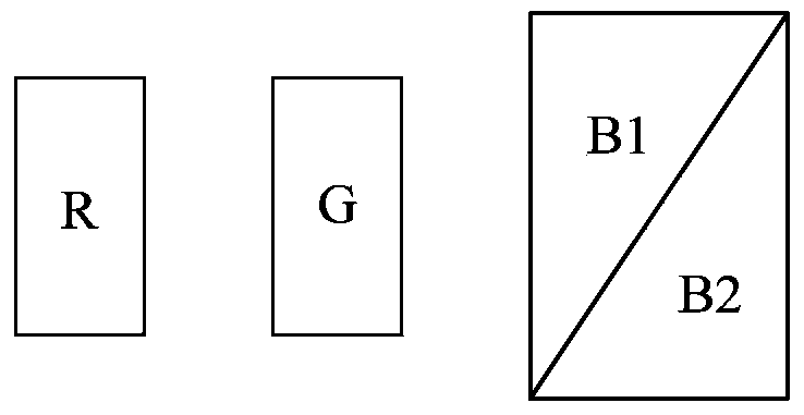
[0105] Step 71: Divide the blue sub-pixel included in the pixel into N blue organic light-emitting diodes OLED, where N is a positive integer greater than 1;
[0106] Step 72: The driving module drives the N blue OLEDs in time division. The driving module includes a driving circuit for time-division driving the blue sub-pixels.
[0107] It can be understood that the time-divisional driving refers to that the blue sub-pixels or the N blue OLEDs are driven to emit light in at least two time periods. For example: N blue OLEDs can emit light independently in N time periods (N is a positive integer greater than 1); it can also be a positive integer within a certain period of time P (2≤P
[0108] In the first embodime...
no. 2 example
[0110] The second embodiment of the driving method of the pixel circuit described in the present invention is used to drive the second embodiment of the pixel circuit described in the present invention, including:
[0111] dividing the blue sub-pixel included in the pixel into N blue organic light-emitting diodes OLED, where N is a positive integer greater than 1;
[0112] When the absolute value of the voltage difference between the current level output terminal connected to a driving unit and the first level output terminal is greater than the absolute value of the lighting voltage of the blue OLED connected to the driving unit, and except the current When the level output terminal and the level output terminals other than the first level output terminal are suspended, the driving unit drives the blue OLED to emit light.
no. 4 example
[0113] The third embodiment of the driving method of the pixel circuit described in the present invention is used to drive the fourth embodiment of the pixel circuit described in the present invention, including:
[0114] dividing the blue sub-pixel included in the pixel into N blue organic light-emitting diodes OLED, where N is a positive integer greater than 1;
[0115] When the absolute value of the voltage difference between the first level output terminal and a level output terminal is greater than the absolute value of the lighting voltage of the blue OLED connected to the level output terminal, and when the N levels When the voltage difference between the level output terminals other than the level output terminal and the first level output terminal among the output terminals is smaller than the absolute value of the lighting voltage of the blue OLED, the driving circuit drives the blue OLED Color OLED emits light.
[0116] The present invention also provides an array ...
PUM
 Abstract
Description
Claims
Application Information
 - Generate Ideas
- Intellectual Property
- Life Sciences
- Materials
- Tech Scout
- Unparalleled Data Quality
- Higher Quality Content
- 60% Fewer Hallucinations
Browse by: Latest US Patents, China's latest patents, Technical Efficacy Thesaurus, Application Domain, Technology Topic, Popular Technical Reports.
© 2025 PatSnap. All rights reserved.Legal|Privacy policy|Modern Slavery Act Transparency Statement|Sitemap|About US| Contact US: help@patsnap.com