

High-voltage vacuum extinction chamber
A vacuum interrupter and high-voltage technology, which is applied in high-voltage air circuit breakers, high-voltage/high-current switches, electrical components, etc., can solve the problem of reduced breaking current capability, tip current containment, and moving contacts that cannot be 1% Guarantee and other issues to achieve the effect of improving life, improving the ability to disconnect current, and avoiding influence
Active Publication Date: 2014-01-01
ZHEJIANG ZIGUANG ELECTRIC APPLIANCE
View PDF6 Cites 5 Cited by
- Summary
- Abstract
- Description
- Claims
- Application Information
AI Technical Summary
Problems solved by technology
This patent improves the service life of the high-voltage vacuum interrupter, but there are still deficiencies
Since there will be protrusions on the surface of the static contact and the moving contact, after the current is disconnected, a sharp discharge will be formed at the protrusions of the static contact and the moving contact, and the shielding cover mentioned above in this patent cannot be effective The containment of the tip current leads to the reduction of the fracture insulation strength of the static contact and the moving contact, which reduces the ability of the vacuum interrupter to break the current
[0004] In addition, the moving contact in the vacuum interrupter is driven by a strong elastic force when the static contact is closed. In theory, the moving contact should be kept on the same axis as the static contact, so that the planar moving contact can be guaranteed. The head and the plane static contact have the largest contact area, but in fact, due to manufacturing and installation errors, the moving contact cannot be guaranteed to move along the axial direction 100%, and the moving contact is instantly contacted by the strong spring. The static contacts are in contact, and the moving contacts that have deviated from the axial direction are difficult to move laterally on the static contacts due to friction. Although the offset is small, it has little impact on the performance of the product in the on state, but in the off When opening, the edge of the moving contact or the static contact will cause more tip discharge phenomena, which will reduce the ability of the vacuum interrupter to break the current instantaneously
Method used
View moreImage
Smart ImageViewing Examples

Examples
Embodiment 2
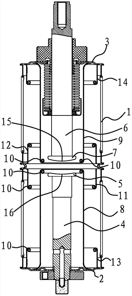
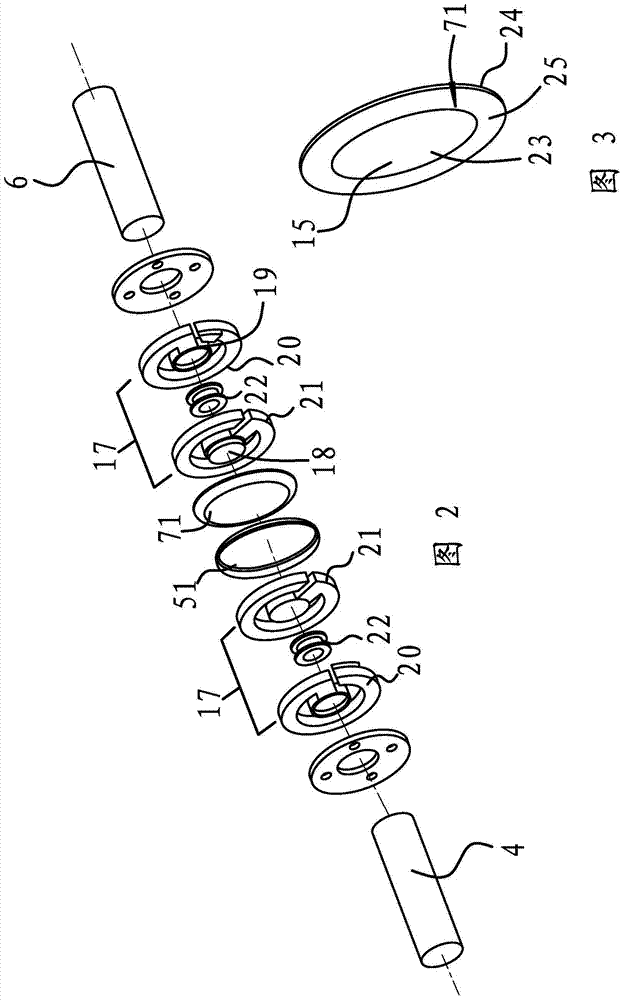
[0030] The content of embodiment 2 is basically the same as that of embodiment 1, the difference is that the adjustment structure includes a spherical positioning surface 15 arranged on the movable contact 7 and a hemispherical concave surface provided on the static contact 5, the hemispherical concave surface The radius of the ball is larger than that of the spherical positioning surface 15, and the spherical positioning surface 15 is opposite to the hemispherical concave surface.
[0031] In addition to these structures, it is also possible to reverse the above-mentioned structures. More broadly, the shape of the top block can be designed as a convex shape with a rounded surface, which can minimize the condition of tip discharge.
Login to View More PUM
 Abstract
The invention provides a high-voltage vacuum extinction chamber, belonging to the technical field of high voltage electrical apparatus insulation, and aiming at realizing the purposes of increasing a transient turn-off current and extinguishing arc quickly. The high-voltage vacuum extinction chamber comprises a glass shade, and a static end cover board and a movable end cover board which are respectively fixed at two ends of the glass shade, wherein a static conducting rod fixed on the static end cover board and a movable conducting rod connected to the movable end cover board in a sliding manner are arranged in the glass shade; the inner end of the static conducting rod is provided with a static contact, the inner end of the movable conducting rod is provided with a movable contact as big as the static contact; a first static shade barrel covering the static contact and the static conducting rod inside, and a first movable shade barrel which is arranged by being symmetric to the first static shade barrel and covers the movable conducting rod inside, are arranged in the glass shade; the inner side faces of the opposite ends of the first static shade barrel and the first movable shade barrel are provided with spiral turned edges, and when the movable contact is disconnected with the static contact, the movable contact can move into the first movable shade barrel. The high-voltage vacuum extinction chamber can realize quick arc extinguishing and improve the instantaneous current interruption capability of the vacuum extinction chamber.
Description
technical field [0001] The invention belongs to the technical field of high-voltage electrical insulation, and relates to a high-voltage vacuum interrupter. Background technique [0002] Vacuum interrupter, also known as vacuum switch tube, is the core component of medium and high voltage power switches. Its principle is to use high-vacuum work to insulate the arc-extinguishing medium, and rely on a pair of contacts sealed in the vacuum to realize the on-off function of the power circuit. At the point where the heads are just separated, the resistance between the electrodes increases sharply and the temperature rises rapidly until the evaporation of the electrode metal occurs. After long-term use, the surface of the moving and static contacts will form a bump, which makes the charge distribution on the surface of the moving and static contacts uneven. When the current is cut off, a tip discharge will be formed, which reduces the fracture insulation strength of the surface o...
Claims
Login to View More Application Information
Patent Timeline
 Patent Type & AuthorityApplications(China)
IPC IPC(8): H01H33/664
Inventor周鹤铭刘志远林海涌
OwnerZHEJIANG ZIGUANG ELECTRIC APPLIANCE