Arc Suppression Circuit

Active Publication Date: 2007-03-01
GE GLOBAL SOURCING LLC
View PDF5 Cites 14 Cited by
  • Summary
  • Abstract
  • Description
  • Claims
  • Application Information

AI Technical Summary

Benefits of technology

[0006] The inventor has discovered that contactor tip life can be extended by incorporating a snubber or arc suppression circuit into the vehicle system such that the arc suppression circuit is arranged to reduce arcing at the contactor tips. More particularly, the inventor has found that the contactor tip erosion from arcing occurs when the contactor tips are opened under load. The arc occurs because of the inductive nature of the dynamic braking circuit. As is well known, current in an inductive circuit tends to attempt to continue to flow when the circuit is opened. This results in a rapid rise in voltage at the open circuit point, such as at the contactor tips, causing the air at the tips to ionize and provide a con

Problems solved by technology

This results in a rapid rise in voltage at the open circuit point, such as at the contactor tips, caus

Method used


Image

  • Arc Suppression Circuit
  • Arc Suppression Circuit

Examples


Embodiment Construction

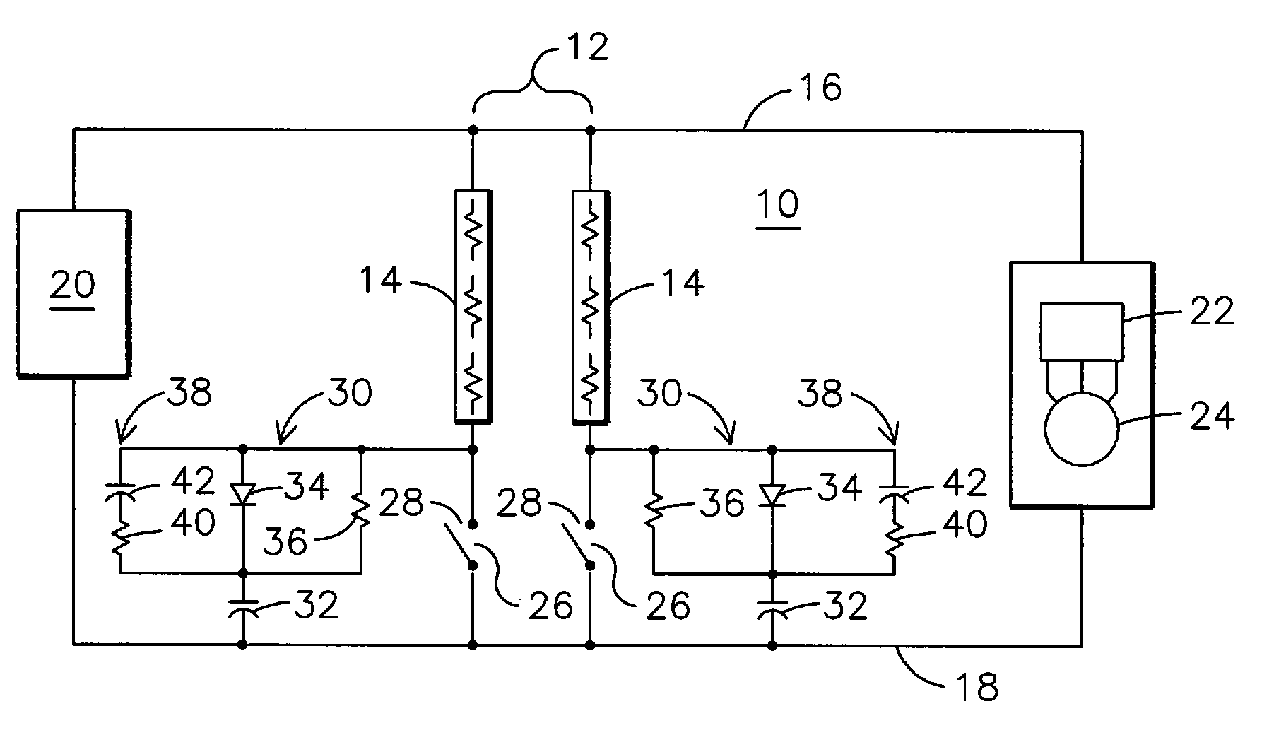
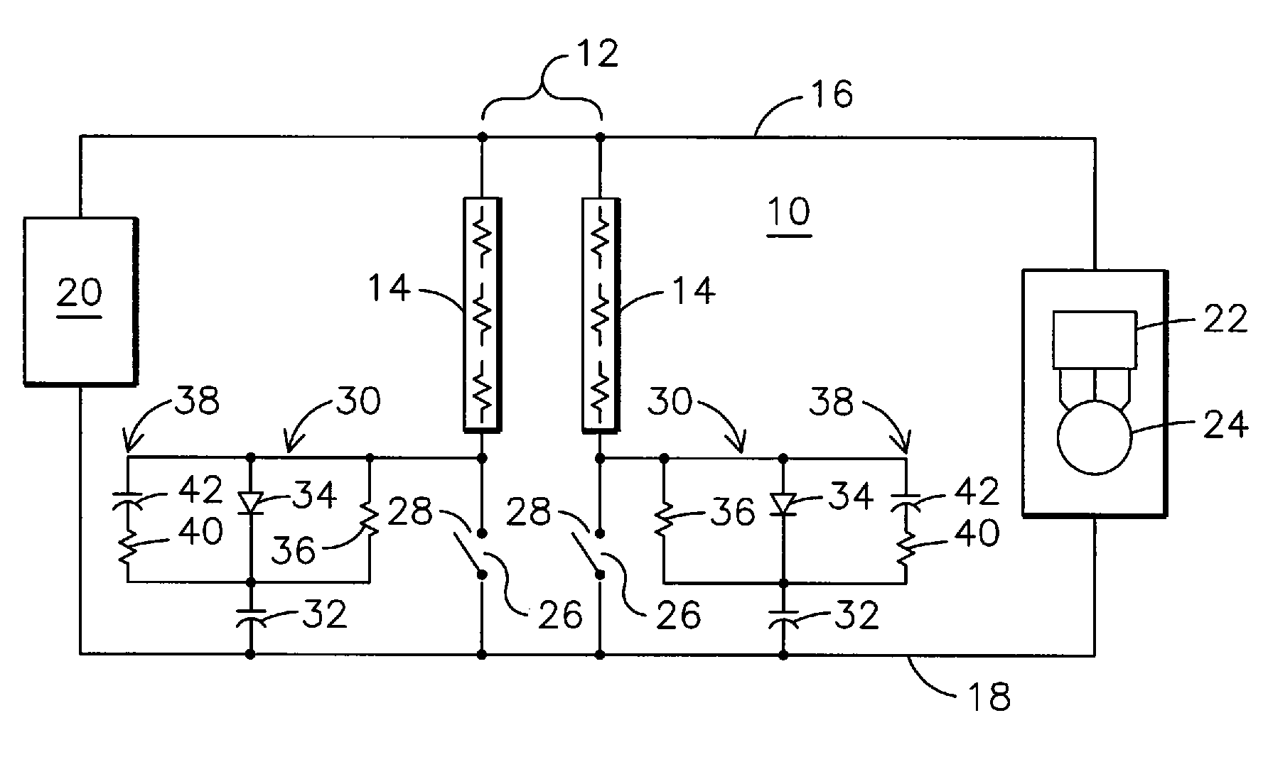
[0009] Referring to the drawing, there is shown a simplified schematic representation of a vehicle dynamic braking system 10 including a dynamic braking grid 12 comprising a plurality of power dissipating resistance elements 14, each connected in series with a contactor 26. While it is common practice in the industry to have a plurality of parallel connected resistance elements 14, each with its own series connected contactor, it will be recognized that the invention is not limited to use in such an arrangement but can be applied to those systems having only a single contactor with a series connected resistance element or elements and to systems having more than two parallel connected elements with corresponding contactors. The elements 14 are connected in one or more parallel circuit paths between a first power buss 16 and a second power buss 18, the busses 16 and 18 being commonly referred to as a DC link since the voltage on the link is generally a DC voltage. At one end of the l...


PUM


Abstract

A contactor arc suppression system for an electric propulsion vehicle having an on-board diesel-electric power generating system for supplying electric power to a plurality of DC electric traction motors for propelling the vehicle in which the traction motors are operable in an electric power generating mode during electrical braking of the vehicle and the vehicle further has a dynamic braking grid selectively coupled in parallel with the traction motors for absorbing the generated electric power during such electrical braking. The system includes at least one contactor having a pair of contact tips arranged to selectively couple the dynamic braking grid into parallel circuit arrangement with the electric traction motors during electrical braking and a snubber circuit having a diode and a first capacitor connected in series circuit arrangement with the snubber circuit connected in parallel with the contact tips of the contactor. A protection circuit for the diode includes a first resistor and a second capacitor connected in series with the protection circuit connected in parallel with the diode. A second resistor is connected in parallel circuit arrangement with the diode for providing a current discharge path for the first capacitor upon closure of the contact tips.

Description

CROSS-REFERENCE TO RELATED APPLICATION [0001] This application claims the benefit of U.S. provisional application No. 60 / 709,967, filed Aug. 19, 2005.FIELD OF THE INVENTION [0002] The present invention relates to dynamic braking circuits for off-highway vehicles and, more particularly, to electronic circuits for suppressing arcing across contactors when the dynamic braking contactors are opened to disengage such braking. BACKGROUND OF THE INVENTION [0003] Off-highway vehicles of the type for which the present invention is intended are typically very large earth-moving machines that use an internal combustion engine, such as a diesel engine, to drive an alternator that produces electric power. The wheels of the vehicle are propelled by electric motors built into the wheels that are powered from the on-board alternator. See, for example, U.S. Pat. No. 3,897,843 for a general description of such a vehicle wheel. Because the vehicles are propelled by electric motors, the internal combus...

Claims


Application Information

Patent Timeline
IPC IPC(8): H02P3/14
CPCH01H9/30
Inventor KOBIELSKI, LOUIS J.
Owner GE GLOBAL SOURCING LLC
Why Eureka
Try Eureka