
Method and a connector arrangement for connecting and disconnecting a generator to a circuit with an existing alternating current

a technology of alternating current and connector arrangement, which is applied in the direction of electric generator control, dynamo-electric converter control, engine starters, etc., can solve the problems of increasing device complexity, affecting performance, and liable to errors, so as to reduce the arc caused when the generator is disconnected.

Inactive Publication Date: 2005-09-08
MICROGEN ENGINE CORP HLDG BV
View PDF9 Cites 13 Cited by
  • Summary
  • Abstract
  • Description
  • Claims
  • Application Information

AI Technical Summary

Benefits of technology

[0008] A Stirling engine is preferably used as the prime mover as it can be initialised by being heated by an external heat source and then remain in a state ready to be brought into operation extremely quickly. Starting the Stirling engine only requires a small amount of energy since the pistons, which are the moving part, are relatively light and can be accelerated from rest very easily. The acceleration of the pistons from rest is continued in the normal operation of the engine, by linear simple harmonic motion.
[0011] By stalling the alternator before disconnecting it from the main, the arcing caused when it is disconnected is substantially reduced.

Problems solved by technology

A number of problems are encountered when connecting and disconnecting an electrical generator to a circuit carrying an existing alternating current such as the main electricity supply.
However, the provision of a control device to monitor the power quality of a generator and then connect the generator to the main electricity supply when the appropriate power quality has been achieved is expensive, increases the complexity of the device and is liable to error.
This arcing wears out the contacts of the switch impairing performance and necessitating regular replacement which is inconvenient and expensive.
Arcing also disturbs the quality of the main electricity signal which is prohibited.
Arcing can also cause damage to other components and the starting of fires and its prevention by for example the provision of an inert gas atmosphere is expensive.

Method used


Image

  • Method and a connector arrangement for connecting and disconnecting a generator to a circuit with an existing alternating current
  • Method and a connector arrangement for connecting and disconnecting a generator to a circuit with an existing alternating current
  • Method and a connector arrangement for connecting and disconnecting a generator to a circuit with an existing alternating current

Examples


Embodiment Construction

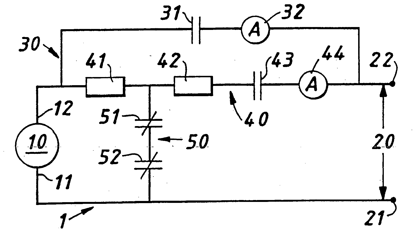
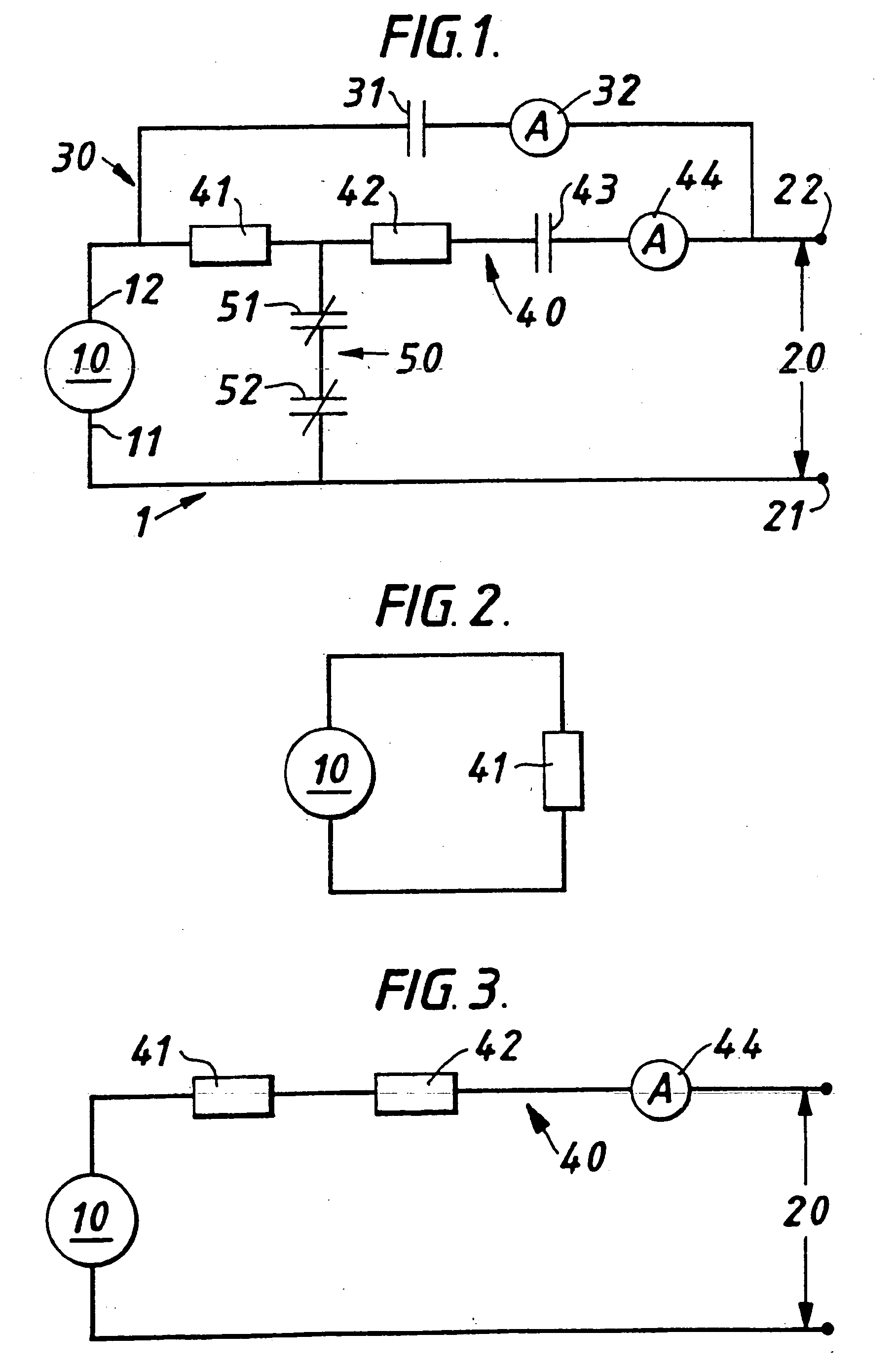
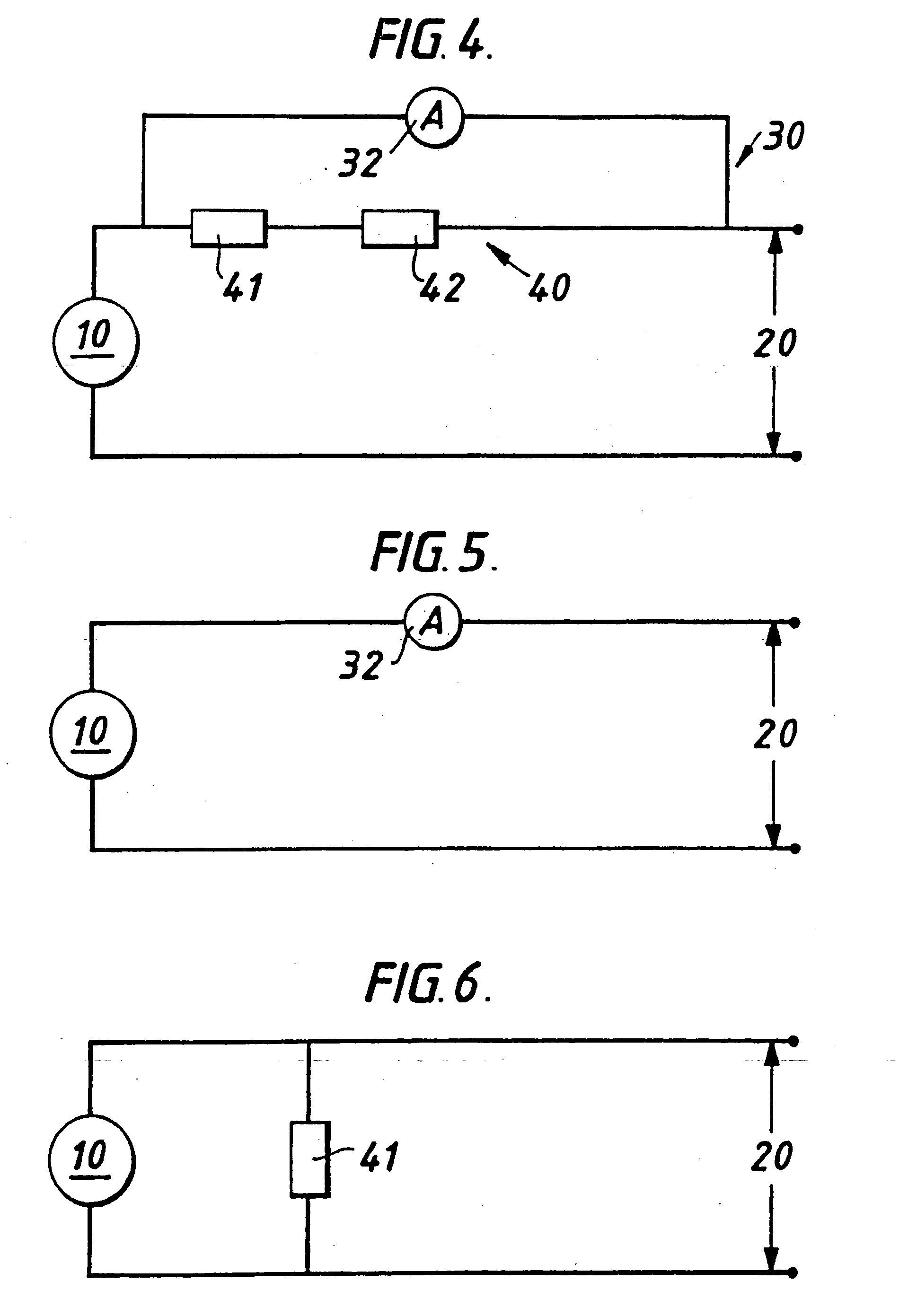
[0020] The prime mover which drives the alternator 10 in the present example shown in FIG. 1 is a Stirling engine as is well known in the art, such as the one described in WO 94 / 04878 for example. However, any other suitable prime mover such as a gas engine, an internal combustion engine or a steam turbine for example would be suitable. Any suitable alternator may be used but in the present example a linear alternator has been found to work particularly well with the reciprocating Stirling engine. In the present example shown in FIG. 1 the main electricity supply 20 between neutral 21 a live terminal 22 acts as the circuit with an existing alternating current. The alternator has two terminals 11, 12 one of which 11 is connected to neutral. The other terminal 12 of the alternator10 is connectable to the live main supply 2 by two parallel paths 30, 40. The first electrical path 30 has a switch 31 and a meter 32 in series and the second electrical path 40 has a first impedance 41, whic...


PUM

PropertyMeasurementUnit
impedanceaaaaaaaaaa
impedanceaaaaaaaaaa
series impedancesaaaaaaaaaa

Abstract

A method and a connector arrangement for connecting and disconnecting an electrical generator, such as a prime mover driven alternator (10), to a circuit with an existing alternating current such as the mains electricity supply (20).

Description

CROSS REFERENCE TO RELATED DOCUMENT [0001] This application is a divisional of U.S. patent application Ser. No. 10 / 221,876, filed Dec. 20, 2002, which in turn is a 371 of PCT / GB01 / 00840, filed on Feb. 27, 2001 and claiming priority of United Kingdom Application No. 0006114.3, filed on Mar. 15, 2000. The entirety of each of the foregoing applications is incorporated herein by reference, and this application is entitled to the benefit of, and claims priority to, each such application.FIELD OF THE INVENTION [0002] The present invention relates to a method and a connector arrangement for connecting and disconnecting an electrical generator such as a prime mover driven alternator to a circuit with an existing alternating current such as the main electricity supply. BACKGROUND OF THE INVENTION [0003] A number of problems are encountered when connecting and disconnecting an electrical generator to a circuit carrying an existing alternating current such as the main electricity supply. [0004...

Claims


Application Information

Patent Timeline
Patent Type & Authority Applications(United States)
IPC IPC(8): F02G1/043F02G1/045H02J3/38F02N11/04H02J3/40
CPCF02G1/043Y10T29/49169Y10T29/49105H02J3/40H02P9/04
Inventor ALDRIDGE, WAYNE KENNETHFRANCIS, GEORGE MCCHESNEYREA, ISOBEL DOROTHY
Owner MICROGEN ENGINE CORP HLDG BV
Learn More