Dual bipolar magnetic field for linear high-voltage contactor in automotive lithium-ion battery systems

a lithium-ion battery and high-voltage contactor technology, applied in relays, electric devices, transportation and packaging, etc., can solve the problem of reducing the tendency of the contact plate to separate from the terminals prematurely, and achieve the effect of reducing the amount of lorentz force, reducing the tendency of arcing associated, and reducing the tendency of formed lorentz forces

Inactive Publication Date: 2014-02-18
GM GLOBAL TECH OPERATIONS LLC
View PDF8 Cites 12 Cited by
  • Summary
  • Abstract
  • Description
  • Claims
  • Application Information

AI Technical Summary

Benefits of technology

[0008]The supplemental magnets used for a relay, switch or related solenoid-based device can be formed to set up a dual bipolar magnetic field in order to reduce the arcing associated with de-energized contacts while simultaneously reducing the tendency of the formed Lorentz forces to impact operation of the electric terminals and contact plate. This dual bipolar configuration, which is formed as a result of two separate magnetic fields created by the sets of magnet pairs, is established in a region adjacent a contactor portion of the relay. This separation of the fields shifts the concentrations of the magnetic density toward a region formed along a side of a chamber that encloses the contact plate and terminals that make up the contactor portion. As a result, the magnetic density is imparted to a smaller contact plate surface area in general, and in particular drastically decreased at the center of the contactor portion. By keeping the amount of contact plate surface area that is exposed to the magnetic field as small as possible, the amount of Lorentz force imparted to the plate is concomitantly kept low, which in turn lessens the chance of an inadvertent separation of the contact plate and the terminals due to such force. The present dual bipolar design also helps maintain control of arc-extinction to improve the stability of the high-voltage contactors, which in turn leads to more robust relay design for high-voltage contactors such as those encountered in lithium-ion battery systems. By separating the magnets and placing them at the four corners around the contactor portion of the relay or switch, the bipolar design formed thereby can significantly decrease the physical effects that are introduced during extreme conditions, such as short-circuit faults.
[0011]In one form, the supplemental magnets are arranged as a dual bipolar set; such construction removes a portion of the Lorentz force from operation on (or coupling to) the contact plate. By reducing the size of the magnetic field that interacts with the contact plate, the magnitude of the Lorentz force (which is downwardly-directed in applications where the movement of the plunger is up and down and the contact plate is arranged above the plunger to also travel up and down) imparted to the contact plate is reduced. This in turn reduces the tendency of the contact plate to separate from the terminals prematurely. This dual bipolar set means that the portion of the field that impinges predominantly on the first portion is generated by a first set while the portion of the field that impinges predominantly on the second portion is generated by a second set. More particularly, the configuration is such that the magnetic field extends substantially orthogonal to a direction of movement of the plunger; in this way, the portion of the field that is generated by the first magnet set extends on one lateral side of the plunger while the portion of the magnetic field that is generated by the second magnet set extends on a substantially opposing lateral side of the plunger. Even more particularly, the two sets of magnets are arranged in a four-square pattern such that a portion of the field that is generated by a first magnet set extends to cover less that one half of the contact plate closest to a first of the terminals while a portion of the field that is generated by a second magnet set extends to cover less that one half of the contact plate closest to a second of the terminals. In another option, the terminals are made up of a first terminal and a second terminal, while the contact plate extends in an elongate direction between the first and second terminals such that the first portion of the contact plate is generally adjacent to the first terminal while a second portion of the contact plate is generally adjacent to the second terminal. More particularly, the contact plate is formed into an elongate shape such that the first portion does not overlap the second portion. By such construction of the contact plate and the magnet sets, a significant portion of the contact plate (in particular, in the region about its middle) has a substantially reduced exposure to the Lorentz force that is generated by the interaction of the magnetic fields and the current flow through the terminals and contact plate. Such construction also means that the imposed Lorentz force and the movement of the solenoid's plunger proceed along a generally parallel path.

Problems solved by technology

This in turn reduces the tendency of the contact plate to separate from the terminals prematurely.

Method used


Image

  • Dual bipolar magnetic field for linear high-voltage contactor in automotive lithium-ion battery systems
  • Dual bipolar magnetic field for linear high-voltage contactor in automotive lithium-ion battery systems
  • Dual bipolar magnetic field for linear high-voltage contactor in automotive lithium-ion battery systems

Examples


Embodiment Construction

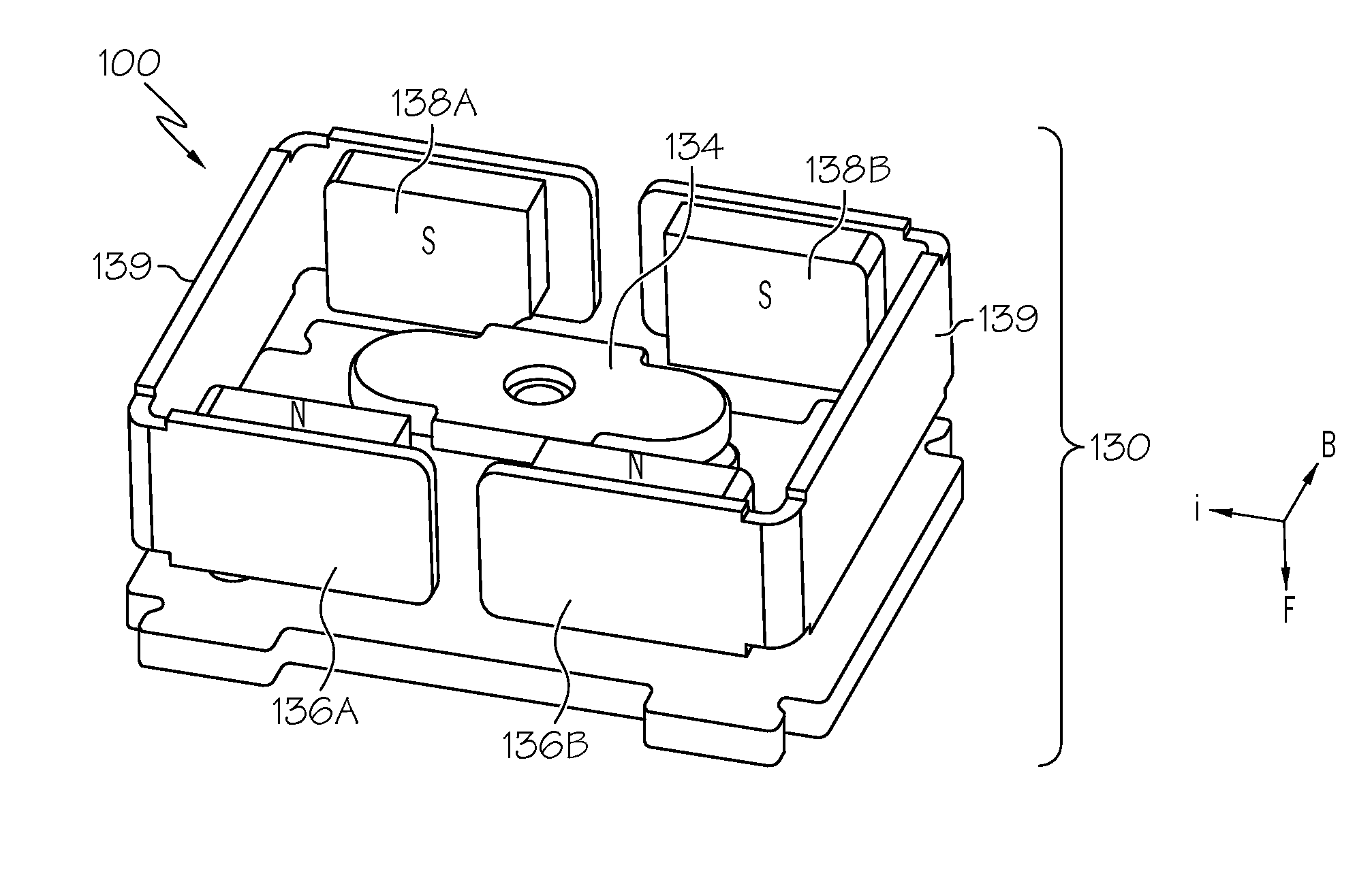
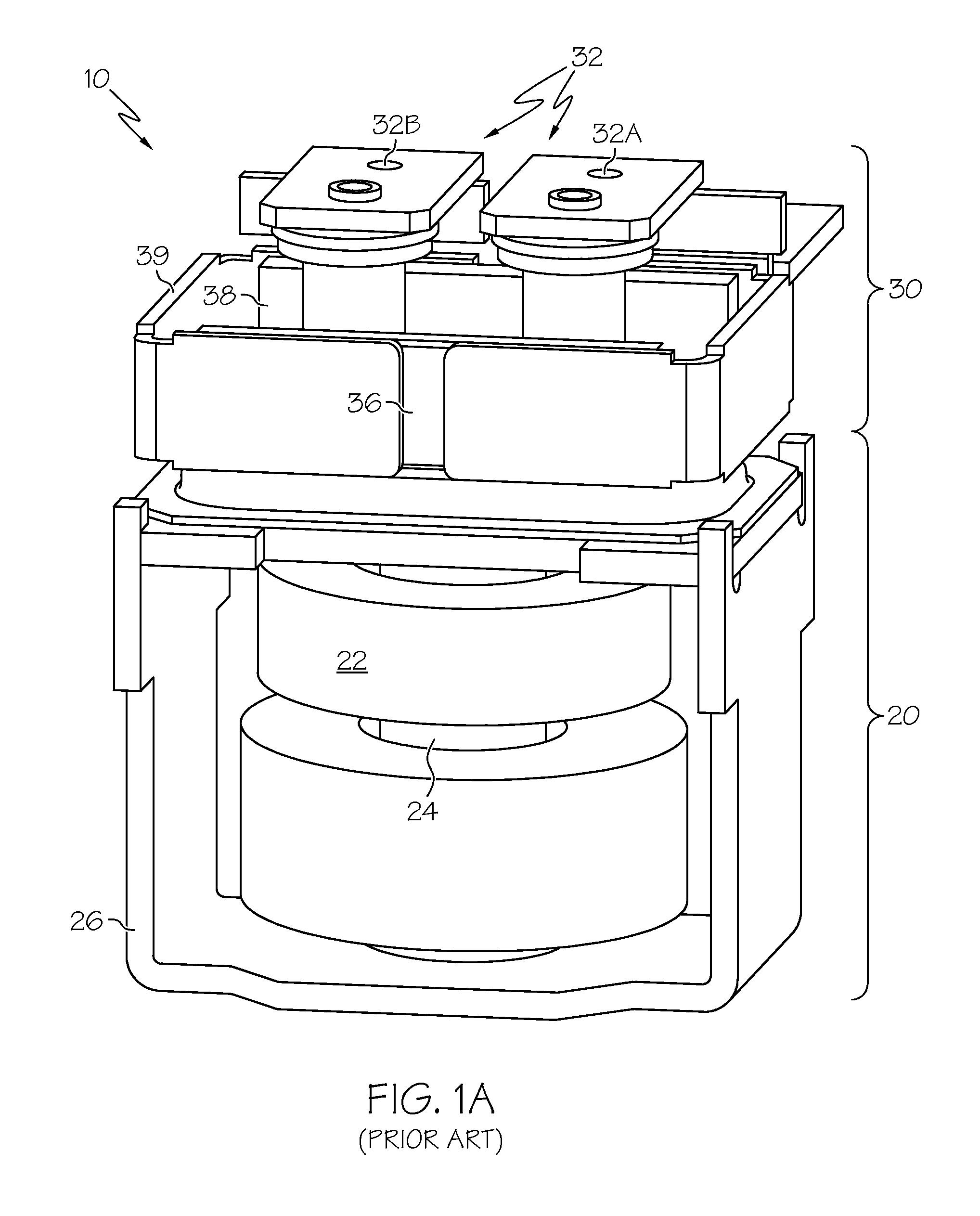
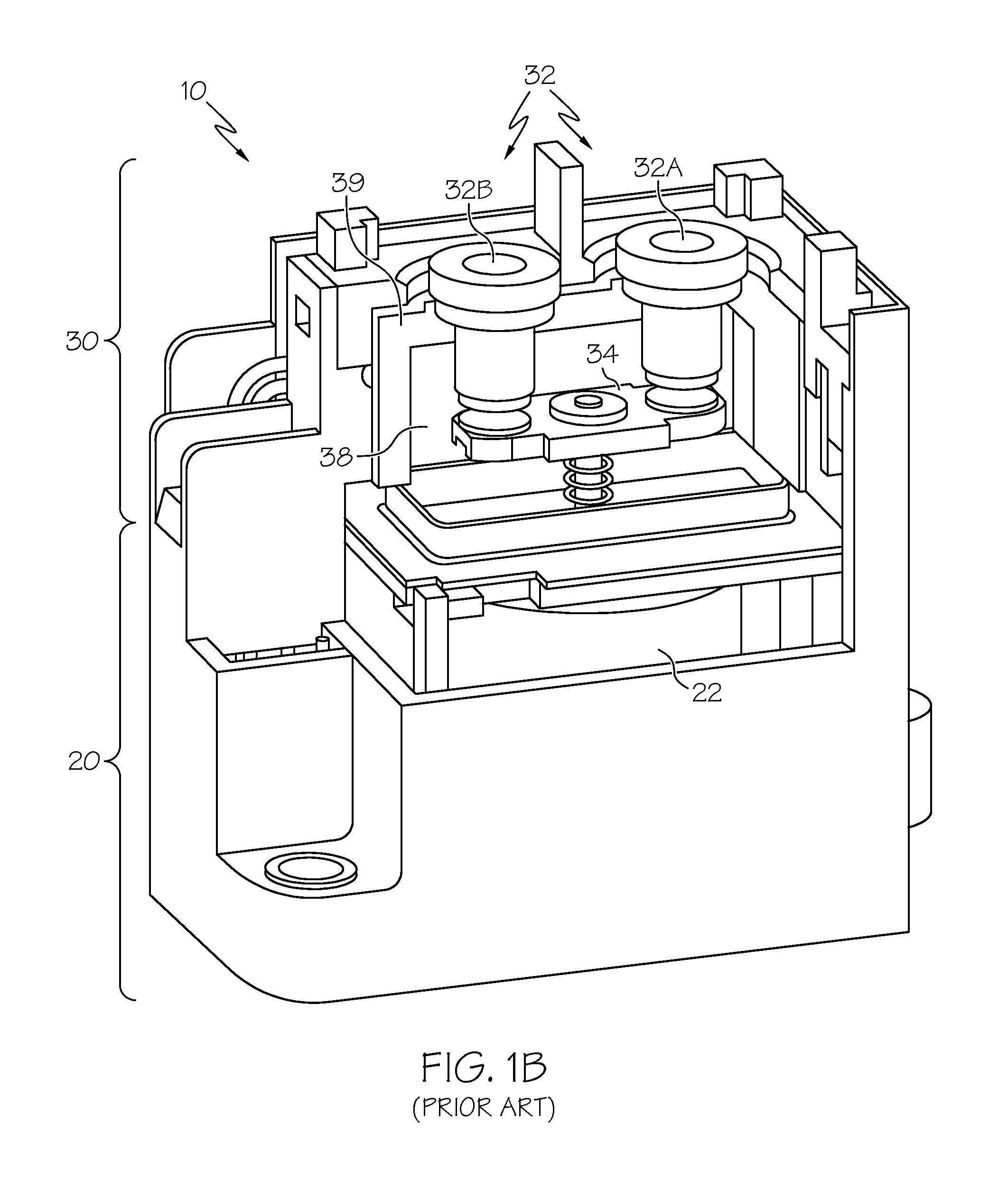
[0025]As discussed above, the effect of arcing on the opening contactor portion of a linear switching assembly (such as a relay) can have a deleterious effect on the assembly and adjacent components. Depending on the configuration of the switching assembly, as well as the voltage and current flowing through the circuit, such arcing occurs very promptly, often on the order of a few hundred microseconds. As mentioned above, prior art approaches have included placing magnets adjacent a contactor portion that includes the contact plates and terminals used to establish a high voltage contactor. Referring first to FIGS. 1A and 1B, a conventional relay 10 (which may also be in the form of a cutout, circuit breaker or related switch) is outfitted with arc-extinguishing magnets (discussed in more detail below). Relay 10 includes a solenoid portion 20 and a contactor portion 30. The solenoid portion 20 includes one or more coils 22 that, when energized, generate a magnetic flow that will long...


PUM


Abstract

A device and method for operating automotive battery system relays and related switches. By creating a dual bipolar magnetic field adjacent the contactor portion of a switching mechanism in the relay, the magnetic field used to promote arc extinguishing is shifted, which in turn reduces the Lorentz force that forms as a byproduct of the field. Such a configuration has the potential for simultaneously maintaining arc-extinguishing capability and improving short-circuit withstanding capability while reducing the tendency of the Lorentz forces to interfere with the operation of a solenoid or other switch-activating mechanisms. Such devices and methods may be used in conjunction with hybrid-powered and electric-powered vehicles.

Description

[0001]This application claims the benefit of the filing date of U.S. Provisional Application No. 61 / 432,329, filed Jan. 13, 2011.BACKGROUND OF THE INVENTION[0002]This invention relates generally to a device and method to reduce the magnitude of a Lorentz force formed on solenoid-based linear contact plate, and more particularly to a device and method to reduce such magnitude while maintaining arc-extinguish features when the contact plate is opened or otherwise de-energized.[0003]Solenoids are often used to open and close relays, switches and related electrical circuit contacts. Typically, a high-voltage contactor employs the solenoid to move a contact plate into selective connection with a pair of stationary current-carrying terminals to complete an electrical circuit between the terminals. The circuit is open (i.e., incomplete) when the solenoid is de-energized, and closed (i.e., complete) when the solenoid is energized. The presence of high voltage and current in the circuit can ...

Claims


Application Information

Patent Timeline
Patent Type & Authority Patents(United States)
IPC IPC(8): B60L3/00H01H47/00
CPCH01H50/546H01H9/443H01H50/36H01H50/18
Inventor HSU, CHIH-CHENGNAMOU, ANDREW J.
Owner GM GLOBAL TECH OPERATIONS LLC
Why Eureka
Try Eureka