Integrated base station antenna

A base station antenna and antenna technology, applied in the direction of independent non-interaction antenna combination, etc., to achieve the effects of reducing mutual influence, flexible resource dynamic allocation and sharing, and ensuring electrical performance indicators

Active Publication Date: 2014-01-01
MOBI TECH SHENZHEN CO LTD +3
View PDF6 Cites 23 Cited by
  • Summary
  • Abstract
  • Description
  • Claims
  • Application Information

AI Technical Summary

Problems solved by technology

[0003] The purpose of the present invention is to provide an active and passive integrated base station antenna that is easy to i

Method used


Image

  • Integrated base station antenna
  • Integrated base station antenna
  • Integrated base station antenna

Examples


Embodiment Construction

[0018] In order to make the object, technical solution and advantages of the present invention clearer, the present invention will be further described in detail below in conjunction with the accompanying drawings and embodiments. It should be understood that the specific embodiments described here are only used to explain the present invention, not to limit the present invention. The implementation of the present invention will be described in detail below in conjunction with specific drawings.

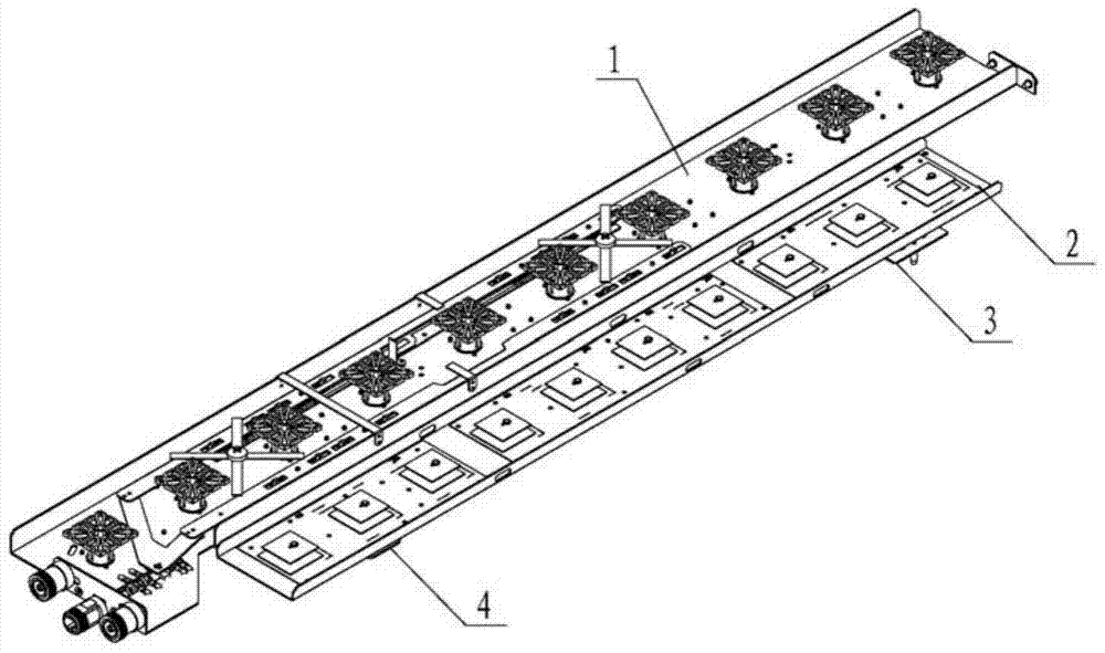
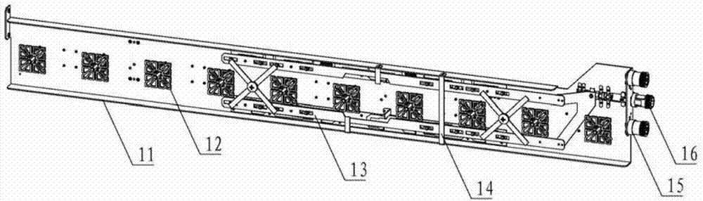
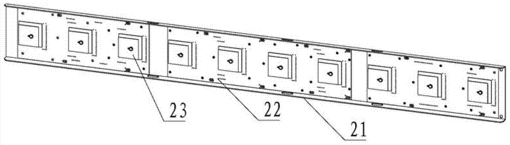
[0019] figure 1 It is a perspective view of the overall structure of an embodiment of an active-passive integrated base station antenna according to an embodiment of the present invention. like figure 1 The shown mainly includes a passive antenna 1 , an active antenna 2 , a first connecting part 3 and a second connecting part 4 . The passive antenna 1 and the active antenna 2 share the same antenna cover; the passive antenna 1 and the active antenna 2 are arranged side by side, an...


PUM


Abstract

The invention discloses an integrated base station antenna which comprises an active antenna part, a passive antenna part and a connection piece. The active antenna part and the passive antenna part share one antenna outer cover and are arranged side by side. The surface of the active antenna part is basically parallel to the surface of the passive antenna part. The active antenna part and the passive antenna part are fixed into a whole through the connection piece. The passive antenna part is designed according to the standard of a mainstream passive antenna. According to the scheme of the active antenna part, a radio frequency part of the base station antenna is integrated inside the antenna to be matched with antenna oscillators through multichannel radio frequency, the spatial beam forming is achieved, and receiving and dispatching of radio-frequency signals are completed; by the different configurations of the active antenna oscillators, the functions such as flexible beam control and MIMO of an actual communication network are achieved, and more flexible resource dynamic configuration and sharing is achieved so that the aims of the optimal performance of the whole network and the lower networking cost of the whole network can be achieved.

Description

technical field [0001] The invention relates to the field of base station antennas for mobile communications, in particular to an integrated base station antenna that combines an active antenna and a passive antenna. Background technique [0002] With more and more network frequency bands and standards, the antenna installation is becoming more and more complicated. It is not only difficult but also expensive for operators to rent antennas. In central cities and hotspot areas, the evolution from 2G / 3G to LTE adopts multi-mode The way of co-station makes space resources very tight. On the other hand, operators are eager to use a simple LTE (wireless network) overlay network to solve the evolution of LTE without affecting existing network services, so as to reduce costs. Supporting multi-band multi-mode, miniaturization, low power consumption, and high-performance base station equipment has become a new pursuit of operators. At present, the expansion of the use of antennas i...

Claims


Application Information

Patent Timeline
IPC IPC(8): H01Q21/28
Inventor 郭亚军侯小强安涛牛磊超
Owner MOBI TECH SHENZHEN CO LTD
Why Eureka
Try Eureka