Braided rope drawing method, porous membrane manufacturing method, and braided rope supplying device

A technology of porous membrane and manufacturing method, applied in chemical instruments and methods, membrane, membrane technology, etc., can solve the problems of inability to supply hollow ropes, rising tension of support body supply, support body supply, etc., and achieve excellent process stability, Suppresses the effect of kinking

Active Publication Date: 2016-01-20
MITSUBISHI CHEM CORP
View PDF13 Cites 0 Cited by
  • Summary
  • Abstract
  • Description
  • Claims
  • Application Information

AI Technical Summary

Problems solved by technology

[0028] In this way, in the case of continuous supply of the hollow rope, there is a problem in operation
[0029] On the other hand, when the hollow rope is wound on the bobbin, if the rotation of the bobbin is stopped, the hollow rope cannot be supplied during this period, and once the production of the porous membrane is stopped, the production efficiency will be poor.
[0030] In addition, when the support body stored by the method of Patent Document 5 is pulled out from the storage container and supplied to the spinning nozzle, entanglement may occur due to being caught on the housing portion of the storage container or the mandrel.
[0031] If the support is entangled, the supply tension of the support will rise sharply, the support will slide in the support feeding mechanism, and the support will not be fed downstream, or the storage container will be lifted, or it will be damaged due to collision with the guide of the support. Or the entangled part falls off and is sent downstream. In these cases, problems such as being caught on the support guide or the spinning nozzle and stopping the running may occur.

Method used


Image

  • Braided rope drawing method, porous membrane manufacturing method, and braided rope supplying device
  • Braided rope drawing method, porous membrane manufacturing method, and braided rope supplying device
  • Braided rope drawing method, porous membrane manufacturing method, and braided rope supplying device

Examples


no. 1 approach

[0118] A first embodiment of the method for producing a porous membrane (also referred to as a porous hollow fiber membrane) of the present invention will now be described in detail with reference to the drawings.

[0119] The method for producing a porous membrane according to the first embodiment of the present invention includes a step of pulling out a hollow braided support body from the storage container by using the storage container as a winding tool (pulling step); A process of coating the membrane-forming stock solution on the outer peripheral surface of the braided support and solidifying the molding stock solution to form a porous membrane layer on the outer peripheral surface of the braided support (coagulation step).

[0120]

[0121] (braided rope support body)

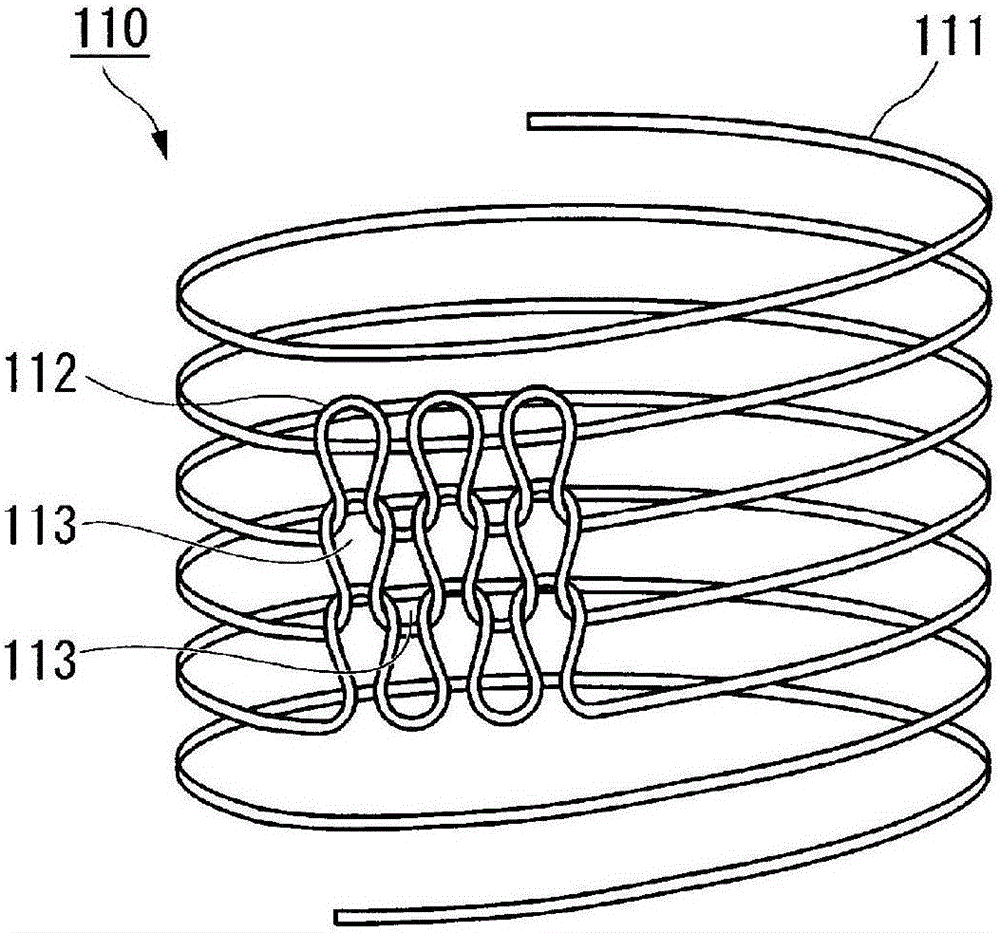
[0122] figure 1 The structure of the braided support body 110 used in this invention is shown.

[0123] The braided support body 110 is a cylindrical (hollow) braided cord in which one yarn 111 is ro...

no. 2 approach

[0276] Next, a second embodiment of the method for producing a porous membrane of the present invention will be described in detail with reference to the drawings.

[0277] In the manufacturing method of the porous membrane of this invention which concerns on 2nd Embodiment, it differs from 1st Embodiment mentioned above in the point which uses a bobbin as a winding tool. The other configurations are the same as those of the first embodiment, so descriptions thereof are omitted.

[0278] (Winding method of the braided rope support body on the winding frame)

[0279] For an example of the winding method of the braided rope support body on the bobbin frame, use Figure 12A with Figure 12B Be explained.

[0280] Figure 12A It is a schematic configuration diagram showing an example of a winding device used when winding a braided cord support body around a bobbin. The winding device 180a of this example has: the bobbin 170 on which the braided rope support body 110 is wound;...

Embodiment approach

[0304] In the second embodiment, the winding of the braided support body on the bobbin is not limited to the method described above. in use Figure 12A In the method of winding device 180a shown, the central axis direction of bobbin 170 is made horizontal to wind braided rope support body 110, but it is also possible to use, for example, Figure 9 The winding device 180b shown in (b) makes the central axis direction of the bobbin 170 vertical, and winds up the braided rope support body 110 as follows.

[0305] Figure 12B The illustrated winding device 180b includes: a bobbin frame 170; a supply guide 182 for supplying the braided rope support body 110 to the bobbin frame 170; A guide fixing fitting 183 capable of reciprocating movement in the central axis direction of the bobbin 170 .

[0306] In the method of winding the braided rope support body 110 on the bobbin 170 using the winding device 180b, first, the bobbin 170 is wound in a state where the center axis direction ...


PUM


Abstract

A method for pulling out a braided rope, in which a braided rope (110) stored in a storage container (120) or wound on a winding frame (170) is pulled out while the storage container (120) or the winding frame (170) is stationary ) out. When sending out the braided rope (110) whose product of twist recovery rate and twisting torque is 14 g·cm or less by this method, the braided rope (110) does not produce kinks when sending out. In the manufacturing method of the porous membrane (26, 150), the membrane-forming stock solution (25) is applied on the outer peripheral surface of the braided cord (110) and solidified to form a porous film on the outer peripheral surface of the braided cord (110). Membrane (151). The supply device (210) has a container (12) and a guide member (214), and pulls the braided rope (110) accommodated in the container (120) toward the guide member (124, 214). According to the present invention, a turntable for rotating the container (120) is not needed, and the braided rope (110) can be fed out with a simple mechanism.

Description

technical field [0001] The present invention relates to a method for producing a porous membrane (porous hollow fiber membrane) having a hollow strength support therein, in which a braided rope support in the porous membrane (porous hollow fiber membrane) is supplied to a spinning nozzle rope supply device. This application claims priority based on Japanese Patent Application No. 2011-024027 filed in Japan on February 7, 2011 and Japanese Patent Application No. 2011-089093 filed in Japan on April 13, 2011, the contents of which are incorporated herein by reference . Background technique [0002] In recent years, a method using an elongated tubular porous membrane has attracted attention as a method of water treatment due to rising concerns about environmental pollution and strengthening of regulations. [0003] In addition, in the fields of food industry, medical treatment and electronic industry, etc., for the purpose of concentration and recovery of useful components, re...

Claims


Application Information

Patent Timeline
Patent Type & Authority Patents(China)
IPC IPC(8): B65H49/02B01D69/08B01D69/10
CPCB01D69/08B01D69/087B01D2323/42B01D2325/40B65H49/12B65H57/20B01D69/10B65H2701/31
Inventor 隅敏则广本泰夫仓科正树品田胜彦
Owner MITSUBISHI CHEM CORP
Why Eureka
Try Eureka