Eureka AIR delivers breakthrough ideas for toughest innovation challenges, trusted by R&D personnel around the world.

Vertical continuous preparing device for carbon nano tube fibers and preparing method

A carbon nanotube fiber, a technology for preparing a device, applied in nanotechnology and other directions, can solve the problems of increasing the complexity of the device, the production cost, and the unfavorable process continuity, and achieve the effects of simple structure, low cost, uniform injection and gasification

Active Publication Date: 2016-03-30
SUZHOU CREATIVE CARBON NANOTECH
View PDF6 Cites 21 Cited by
  • Summary
  • Abstract
  • Description
  • Claims
  • Application Information

AI Technical Summary

Problems solved by technology

In terms of the development of vertical continuous carbon nanotube fiber preparation equipment, the team of Professor Li Yali of Tianjin University used a traditional injection needle to inject liquid-phase carbon source, and the liquid-phase carbon source was brought into the high-temperature reactor by air flow for the preparation of carbon nanotube fiber , the liquid-phase carbon source injector method in this method is simple, but the liquid-phase carbon source is sent to the reaction system drop by drop, which is not conducive to the continuity of the subsequent process
In the prior art, someone added a liquid-phase carbon source injector temperature control device or a liquid-phase carbon source injector atomization device in the continuous carbon nanotube fiber preparation device to improve the uniformity and stability of carbon source injection, But at the same time, it increases the complexity of the device and the production cost

Method used


Image

  • Vertical continuous preparing device for carbon nano tube fibers and preparing method
  • Vertical continuous preparing device for carbon nano tube fibers and preparing method

Examples


preparation example Construction

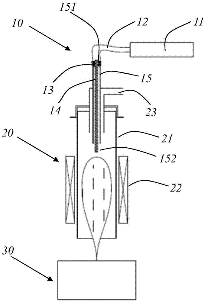
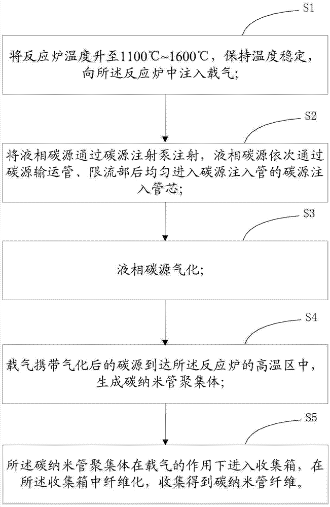
[0037] to combine figure 1 and figure 2 , to introduce a specific embodiment of the method for preparing carbon nanotube fibers of the present invention. In this embodiment, the method specifically includes:

[0038] S1. Raise the temperature of the reaction furnace to 1100° C. to 1600° C., keep the temperature stable, and inject carrier gas into the reaction furnace. In this embodiment, the preparation of carbon nanotube aggregates is carried out in a tubular furnace 20 by using the floating catalytic chemical vapor deposition method, the carrier gas is a mixed gas of hydrogen and nitrogen or hydrogen and an inert gas, and the volume percentage of hydrogen is 10~ 100%, the inert gas is argon or helium, and the flow rate of the carrier gas is 2~10L / min.

[0039] S2. Inject the liquid-phase carbon source through the carbon source injection pump, and the liquid-phase carbon source passes through the carbon source transport pipe, the flow limiting part, and then evenly enters...

Embodiment 1

[0046] Use the mixture of ethanol, ferrocene and thiophene as the liquid-phase carbon source, heat the reaction furnace to 1100°C, and inject it through the carbon source injection pump. The carbon source that enters the carbon source injection tube is injected into the tube core, the mixed gas of hydrogen and argon is used as the carrier gas, the flow rate of the carrier gas is 2L / min, and the continuous collection time is 1 hour. The carbon nanotube fibers are continuously collected by the roller shaft, and finally Continuous 100m carbon nanotube fiber material can be obtained.

Embodiment 2

[0048] Use ethanol, ferrocene, and thiophene mixture as the liquid-phase carbon source, heat the reaction furnace to 1300°C, and inject it through the carbon source injection pump. The carbon source that enters the carbon source injection tube is injected into the tube core, the mixed gas of hydrogen and argon is used as the carrier gas, the flow rate of the carrier gas is 6L / min, and the continuous collection time is 5 hours. The carbon nanotube fibers are continuously collected by the roller shaft, and finally Continuous 800m carbon nanotube fiber material can be obtained.


PUM


Abstract

The invention provides a vertical continuous preparing device for carbon nano tube fibers. The vertical continuous preparing device comprises a carbon source injector, a tube furnace and a collecting box communicated with the tube furnace. The carbon source injector comprises a carbon source injection pump, a carbon source injection tube, a carbon source conveying tube and a flow limiting part, wherein one end of the carbon source injection tube is located in the tube furnace, the carbon source injection pump and the carbon source injection tube are communicated through the carbon source conveying tube, and the flow limiting part is arranged between the carbon source conveying tube and the carbon source injection tube. The carbon source injection pump injects a liquid-phase carbon source into the tube furnace through the carbon source conveying tube and the carbon source injection tube, a carbon source injection tube core is further arranged in the carbon source injection tube, one end of the carbon source injection tube core is arranged in the flow limiting part, and the other end of the carbon source injection tube core protrudes and stretches out of the carbon source injection tube. Compared with the prior art, the carbon source injector which is simple in structure and low in cost is adopted so that the liquid-phase carbon source can be uniformly injected and gasified, and finally the purpose of stably and continuously preparing the carbon nano tube fibers is achieved.

Description

technical field [0001] The invention relates to the field of nanomaterial manufacturing, in particular to a preparation device and method for vertical continuous carbon nanotube fibers. Background technique [0002] Carbon nanotube fiber materials have excellent mechanical, thermal and electrical properties, and have broad application prospects in the preparation of lightweight, high-strength, high-conductivity multifunctional fiber materials. Carbon nanotube fibers can be synthesized by floating catalysis, using liquid carbon sources such as ethanol, adding ferrocene and other catalysts, and passing them into a high-temperature tube furnace under the environment of hydrogen and nitrogen or hydrogen and inert gas carrier gas. Fibers (Li et al. Science 2004 and US Patent 2005 / 006801-A1). In recent years, the development of industrialized preparation technology of floating catalytic carbon nanotube fiber technology has received widespread attention. The floating carbon nanot...

Claims


Application Information

Patent Timeline
IPC IPC(8): C01B31/02B82Y40/00
Inventor 勇振中李志许超李清文
Owner SUZHOU CREATIVE CARBON NANOTECH
Why Eureka
Eureka Blog
Learn More