Magnetic antenna

A magnetic antenna and magnetic technology, applied to loop antennas with ferromagnetic material cores, instruments, calculations, etc., can solve the problems of transmission and reception, magnetic antenna characteristic changes, characteristic deviations, etc., to reduce manufacturing costs and improve mass production , the effect of suppressing deviation

Active Publication Date: 2008-06-25
TODA IND
View PDF2 Cites 25 Cited by
  • Summary
  • Abstract
  • Description
  • Claims
  • Application Information

AI Technical Summary

Problems solved by technology

[0007] However, in the above-mentioned magnetic antenna applied to RFID tags, when the coil of the winding (winding) comes into contact with a metal object, the contact surface between the winding and the metal plate becomes unstable, resulting in a problem that the characteristics vary.
On the other hand, in the reader / writer for RFID tags, it is desired to use a magnetic antenna that can transmit and receive signals with only one electrode. Generates a magnetic field, so there is a problem of sending and receiving signals at the two poles that are separated
In addition, in order to solve this problem, an improved magnetic antenna has been developed. However, in this magnetic antenna, as in the above case, when the coil using a winding such as an enamelled wire comes into contact with a metal object, its characteristics are also poor. There will be a problem of deviation
[0008] Whether it is applied to RFID tags or readers, the winding antenna has the problem of poor mass production.
Moreover, if the original magnetic antenna is close to a metal object, there will be a problem that the characteristics of the magnetic antenna will change and the resonance frequency will change. In order to obtain resonance at the target frequency, it must be pasted on a metal plate and aligned separately. Frequency to adjust

Method used


Image

  • Magnetic antenna
  • Magnetic antenna
  • Magnetic antenna

Examples


Embodiment 1

[0059] The magnet antenna of the present invention is manufactured by using LTCC technology. First, the magnetic layer 15 is produced. In the making process of magnetic layer 15, use ball mill to mix Ni-Zn-Cu ferrite calcined powder (Fe 2 o 3 : 48.5 mol%, NiO: 25 mol%, ZnO: 16 mol%, CuO: 10.5 mol%. ) 100 parts (weight unit), butyral (butyral) resin 8 parts (weight unit), plasticizer 5 parts (weight unit), solvent 80 parts (weight unit) to prepare the adhesive liquid. The obtained adhesive liquid (slurry) was applied on a PET film using a doctor blade, and sheet molding was performed so that the side length was 150 mm square and the thickness at the time of firing was 0.1 mm.

[0060] In addition, in the manufacturing process of the insulating layer 16, the same as above, use a ball mill to mix Zn-Cu ferrite calcined powder (Fe 2 o 3 : 48.5 mol%, ZnO: 41 mol%, CuO: 10.5 mol%) 100 parts, butyral resin 8 parts, plasticizer 5 parts, solvent 80 parts to prepare the adhesive li...

Embodiment 2

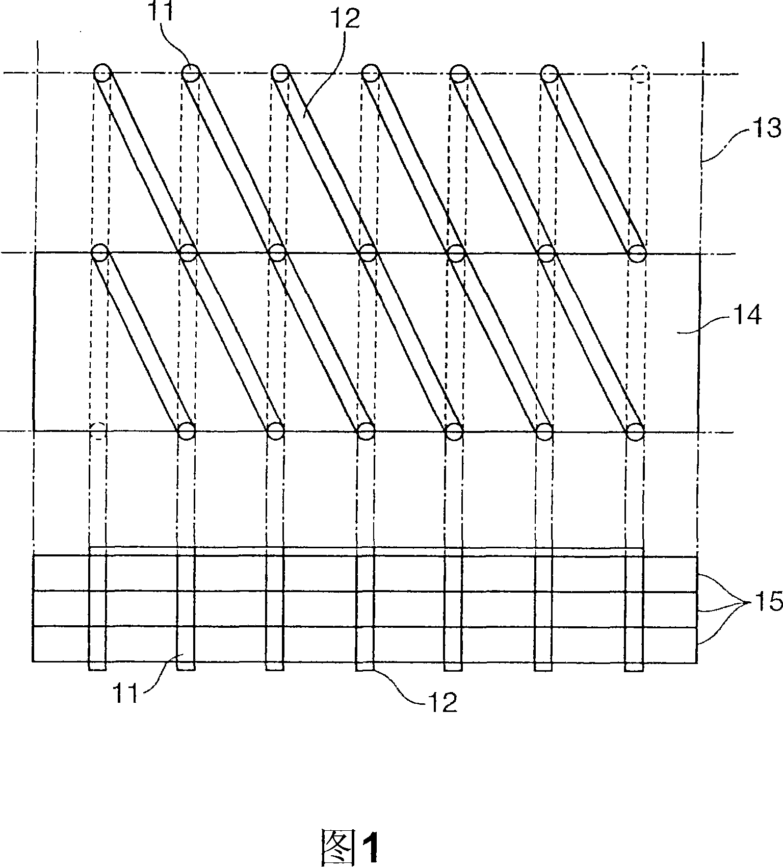
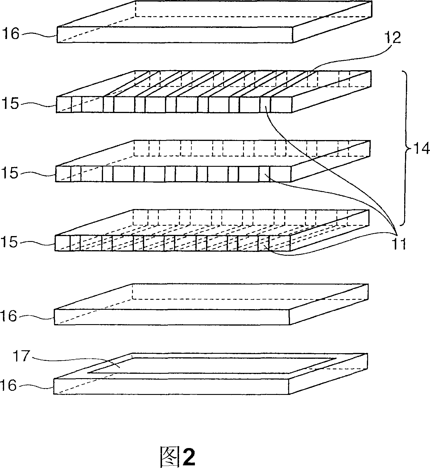
[0072] The same green sheet as the magnetic layer 15 as in Example 1, and a green sheet as the insulating layer 16 made of glass ceramics instead of Zn—Cu ferrite were used. As shown in FIG. 3 , five sheets of green sheets constituting the magnetic layer 15 are laminated, a through hole 11 is opened thereon and silver paste is filled therein, and silver paste is printed on two surfaces perpendicular to the through hole 11, The coil 14 is thus formed.

[0073] Next, a green sheet constituting the insulating layer 16 is laminated on one side of the coil 14 . At this time, the conductive layer 17 is printed on the insulating layer 16 with silver paste. In addition, another insulating layer 16 is laminated on the other surface of the coil 14. On the insulating layer 16, through holes 11 are opened for connection with both ends of the coil 14, and silver paste is filled therein. On the surface of the insulating layer where the hole 11 is perpendicular, the coil lead terminals 19 ...

Embodiment 3

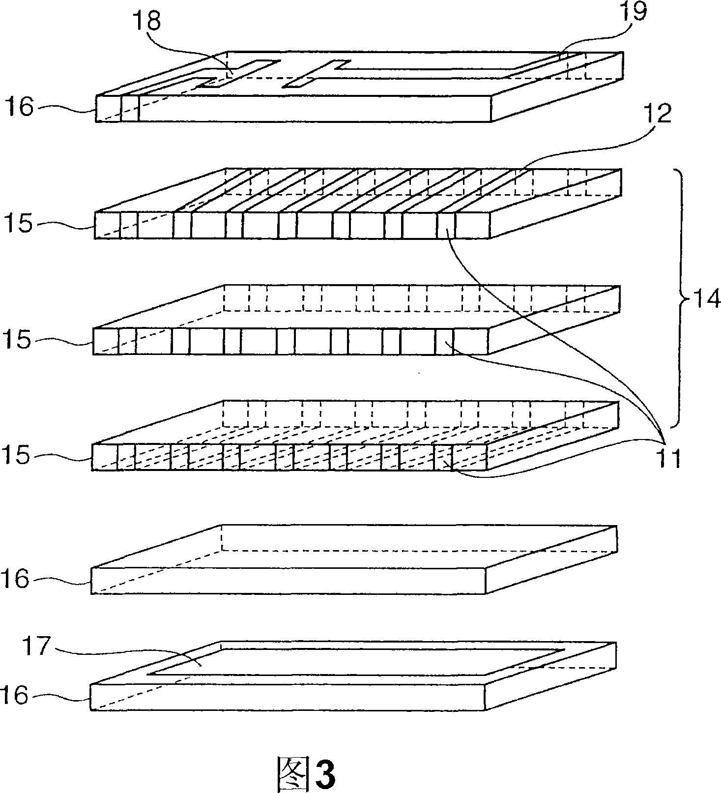
[0077] The same green sheet as the magnetic layer 15 and the green sheet as the insulating layer 16 as in Example 1 were used. As shown in FIG. 4 , five green sheets constituting the magnetic layer 15 are stacked, through-holes 11 are opened thereon and silver paste is filled therein, and silver paste is printed on both sides perpendicular to the through-holes 11, thus forming Coil 14.

[0078] Next, a green sheet constituting the insulating layer 16 is laminated on the lower surface of the coil 14 . At this time, the conductive layer 17 is printed on the insulating layer 16 using silver paste. Further, a green sheet serving as the magnetic layer 15 is laminated under the insulating layer 16 . A green sheet constituting the insulating layer 16 is laminated on the upper surface of the coil 14 . On the top of the insulating layer 16, in order to be connected with the two ends of the coil 14, a through hole 11 is opened, and silver paste is filled therein, and, on the surface ...


PUM


Abstract

There is provided a magnetic antenna, suitable for use in an RFID tag and an RFID tag reader / writer, which operates stable even if brought close to a metallic object and suitable for mass-production, and a board mounted with the magnetic antenna. The magnetic antenna has a coil comprising a magnetic layer and a conductive layer provided on the magnetic layer via an insulating layer. Alternatively, the magnetic antenna has a plurality of coils each comprising a magnetic layer having a square or rectangular shape and arranged radially. One ends of the coils are connected in series or parallel to one another by the magnetic layers thereof such that the coils have the same polarity. An insulating layer is provided on one or both outer surface of the coils, and a conductive layer is provided on an outer surface of at least one of the insulating layers. The magnetic antenna is produced using an LTCC technology.

Description

technical field [0001] The present invention relates to a magnetic antenna. Specifically, it is a magnetic antenna for communication using a magnetic field component, and the magnetic antenna can send and receive signals with good sensitivity even when it is added to an object made of metal. . The magnetic antenna of the present invention is particularly suitable for RFID tags and readers / writers for RFID tags. Background technique [0002] For an antenna that uses a magnetic body to send and receive electromagnetic waves (hereinafter referred to as a "magnetic antenna"), a wire is wound on a magnetic body to form a coil, and the magnetic field component entering from the outside penetrates the magnetic body and is induced in the coil. , an antenna that converts magnetic field components into a voltage (or current), has been widely used in small radios or televisions. In addition, magnetic antennas are also used in non-contact object identification devices called RFID tags...

Claims


Application Information

Patent Timeline
Patent Type & Authority Applications(China)
IPC IPC(8): H01Q7/08G06K17/00G06K19/00H01Q1/38
Inventor 木村哲也佐藤由郎
Owner TODA IND
Why Eureka
Try Eureka