Screw expander

A screw expander and screw technology, applied in mechanical equipment, engine components, machines/engines, etc., can solve problems such as low power generation efficiency, impracticality, and loss

Inactive Publication Date: 2014-01-01
KOBE STEEL LTD
View PDF5 Cites 4 Cited by
  • Summary
  • Abstract
  • Description
  • Claims
  • Application Information

AI Technical Summary

Problems solved by technology

In principle, the binary power generation system has low power generation efficiency, so it is hardly practical except for cases where there is a large-capacity heat source, although the temperature cannot cause water vapor to flash like g

Method used


Image

  • Screw expander
  • Screw expander
  • Screw expander

Examples


Embodiment Construction

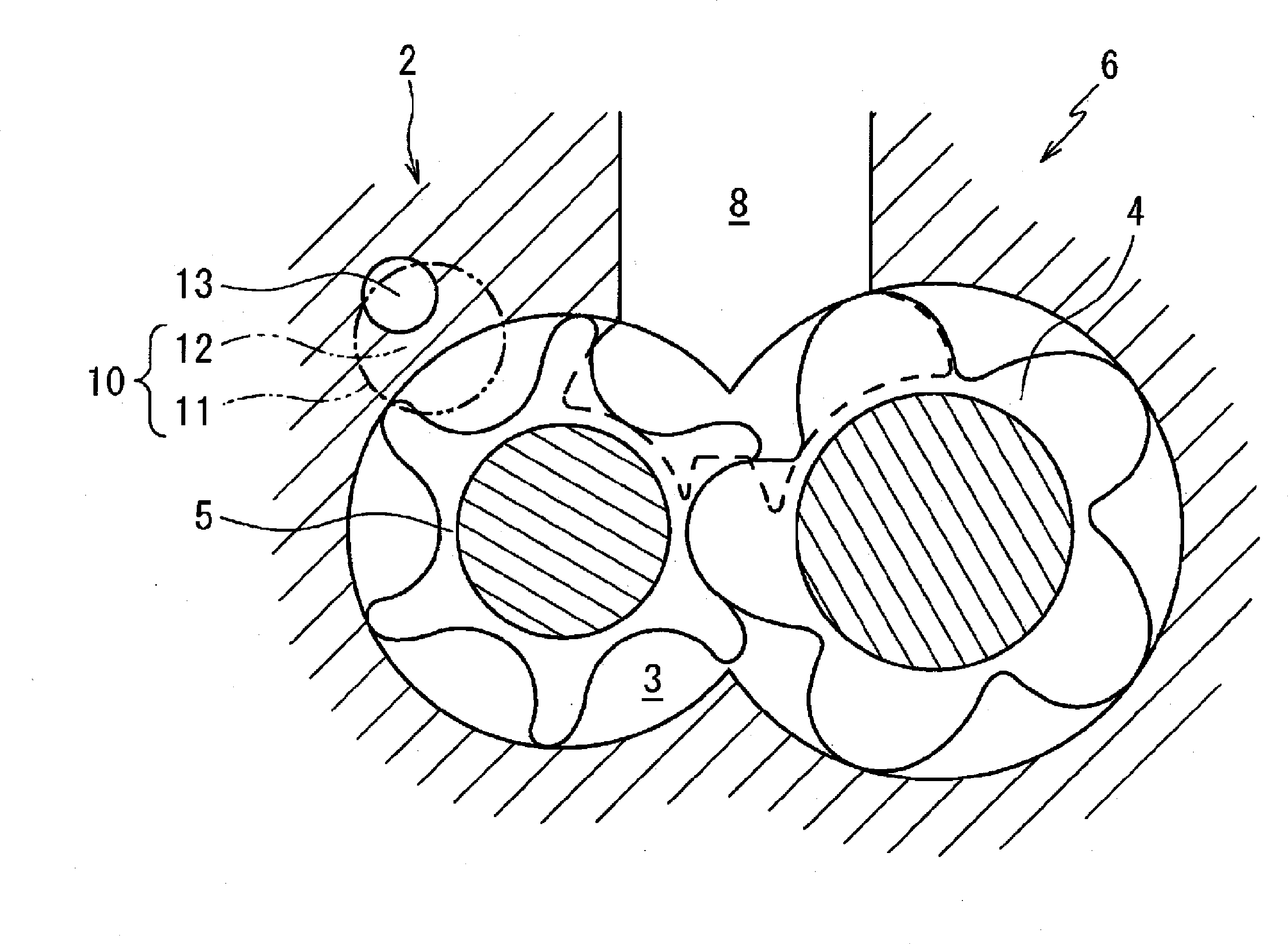
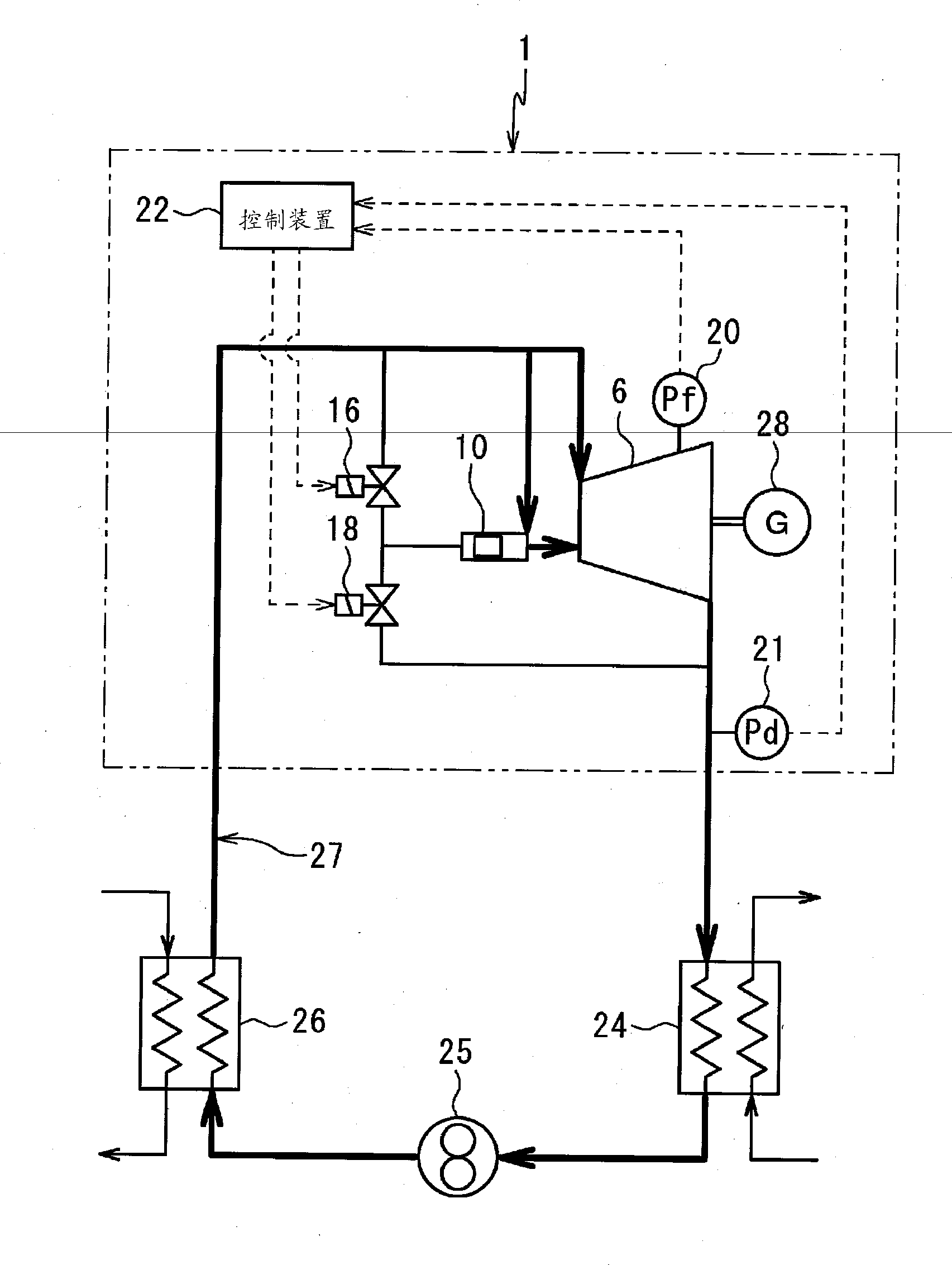
[0025] Hereinafter, embodiments of the present invention will be described with reference to the drawings. exist figure 1 In , the screw expander 1 as the first embodiment of the present invention is shown.

[0026] The screw expander 1 has an expander main body 6 that accommodates a pair of male and female screw rotors 4 , 5 engaged with each other in a rotor chamber 3 formed in a housing 2 . A high-pressure gas is supplied to the rotor chamber 3 from a gas supply path 8 connected to the external flow path 7 . And, the gas is exhausted from the rotor chamber 3 through the exhaust flow path 9 .

[0027] The screw rotors 4 and 5 divide the space in the rotor chamber 3 by their teeth, and define a plurality of expansion spaces between the supply flow path 8 and the exhaust flow path 9 . The volume of the expansion space gradually increases from the supply flow path 8 toward the exhaust flow path 9 as the screw rotors 4 and 5 rotate. Therefore, the screw rotors 4 and 5 are ro...


PUM


Abstract

In order to reduce loss due to a difference between an internal expansion ratio and an operational expansion ratio, a screw expander (1) is provided with: an internal-discharge-gas pressure detector (20) for detecting the pressure (Pf) in an expansion space measured immediately before the expansion space is connected to a gas discharge channel (9); an operation-discharge-gas pressure detector (21) for detecting the pressure (Pd) within the gas discharge channel (9); a bypass channel (13) for connecting a gas supply channel (8) and the expansion space located at a position at which the expansion space can be separated from the gas supply channel (8) and the gas discharge channel (9); a valve mechanism (10) which can shut off the bypass channel (13); and a control device (22) which closes the valve mechanism (10) when a detection value (Pf) detected by the internal-discharge-gas pressure detection means (20) is higher than or equal to a detection value (Pd) detected by the operation-discharge-gas pressure detection means (21), and which opens the valve mechanism (10) when the detection value (Pf) detected by the internal-discharge-gas pressure detection means (20) is lower than the detection value (Pd) detected by the operation-discharge-gas pressure detection means (21).

Description

technical field [0001] The present invention relates to screw expanders. Background technique [0002] Power generation systems that drive generators by flash evaporation of water vapor have been widely introduced, but conventionally, there are many large-scale installations that use turbocharging or axial flow turbines. Recently, however, from the viewpoint of energy saving, there has been an increasing demand for small-scale power generation systems that recover exhaust heat and generate power. [0003] In small-scale facilities, it is known that, for example, it is more efficient to use a screw expander instead of a turbine as described in Non-Patent Document 1. In general, in a screw expander, the ratio of the volume at the time of air supply to the volume at the time of exhaust of the expansion space divided by the screw rotor into the rotor chamber is determined by the shape of the machine. The ratio of the pressure in the expansion space at the moment of isolation (...

Claims


Application Information

Patent Timeline
IPC IPC(8): F01C1/16F01C20/26F01C21/18
CPCF01C21/18F01C20/26F01C1/16
Inventor 壶井升松村昌义
Owner KOBE STEEL LTD
Why Eureka
Try Eureka