Constant velocity universal joint

A constant velocity universal joint and guide groove technology, applied in the direction of gear transmission mechanism, elastic coupling, clutch, etc., can solve the problems of constant velocity universal joint enlargement, shoulder defect, uneven depth of guide groove, etc. Achieve the effects of avoiding enlargement, preventing shoulder defects, and realizing load capacity and durability.

Inactive Publication Date: 2009-07-22
NTN CORP
View PDF1 Cites 4 Cited by
  • Summary
  • Abstract
  • Description
  • Claims
  • Application Information

AI Technical Summary

Problems solved by technology

[0006] As mentioned above, due to the offset of the guide grooves 2b and 3b, the depths of the two guide grooves are not uniform in the axial direction.
Therefore, when the torque transmission ball 4 transmits a high load in a place where the guide groove is shallow (at a large active angle), the contact ellipse caused by the contact with the torque transmission ball 4 increases, and the contact ellipse goes beyond the guide where the gravity is concentrated. Grooved shoulder, resulting in possible defection of the shoulder
As a countermeasure, it is conceivable to increase the diameter of the torque transmission ball 4 or the pitch circle diameter (PCD) to reduce the surface pressure. However, the increase in the outer diameter of the outer ring 2 will cause the disadvantage of increasing the constant velocity universal joint.

Method used


Image

  • Constant velocity universal joint
  • Constant velocity universal joint
  • Constant velocity universal joint

Examples


Embodiment Construction

[0047] Hereinafter, embodiments of the present invention will be described in detail with reference to the drawings.

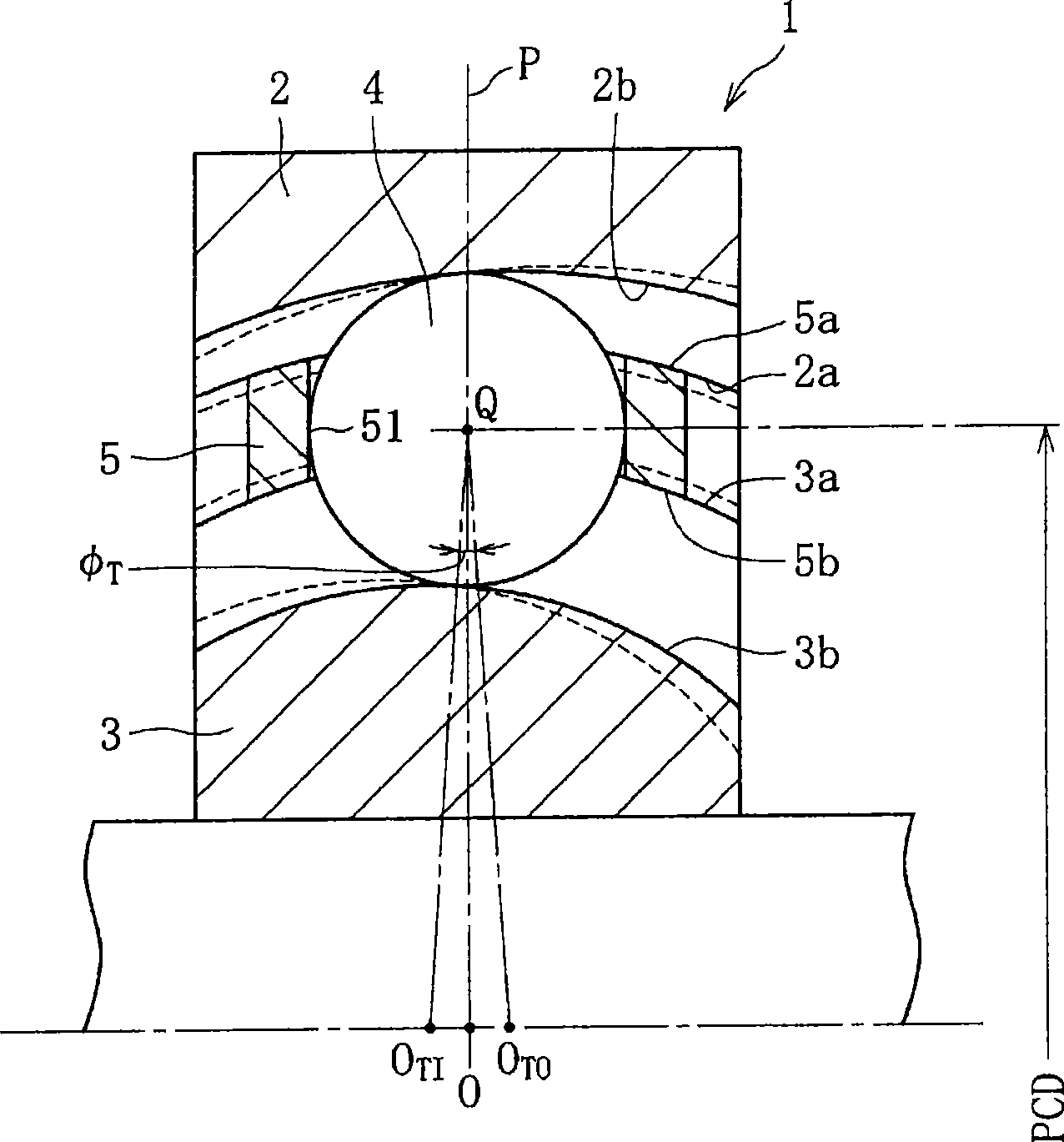
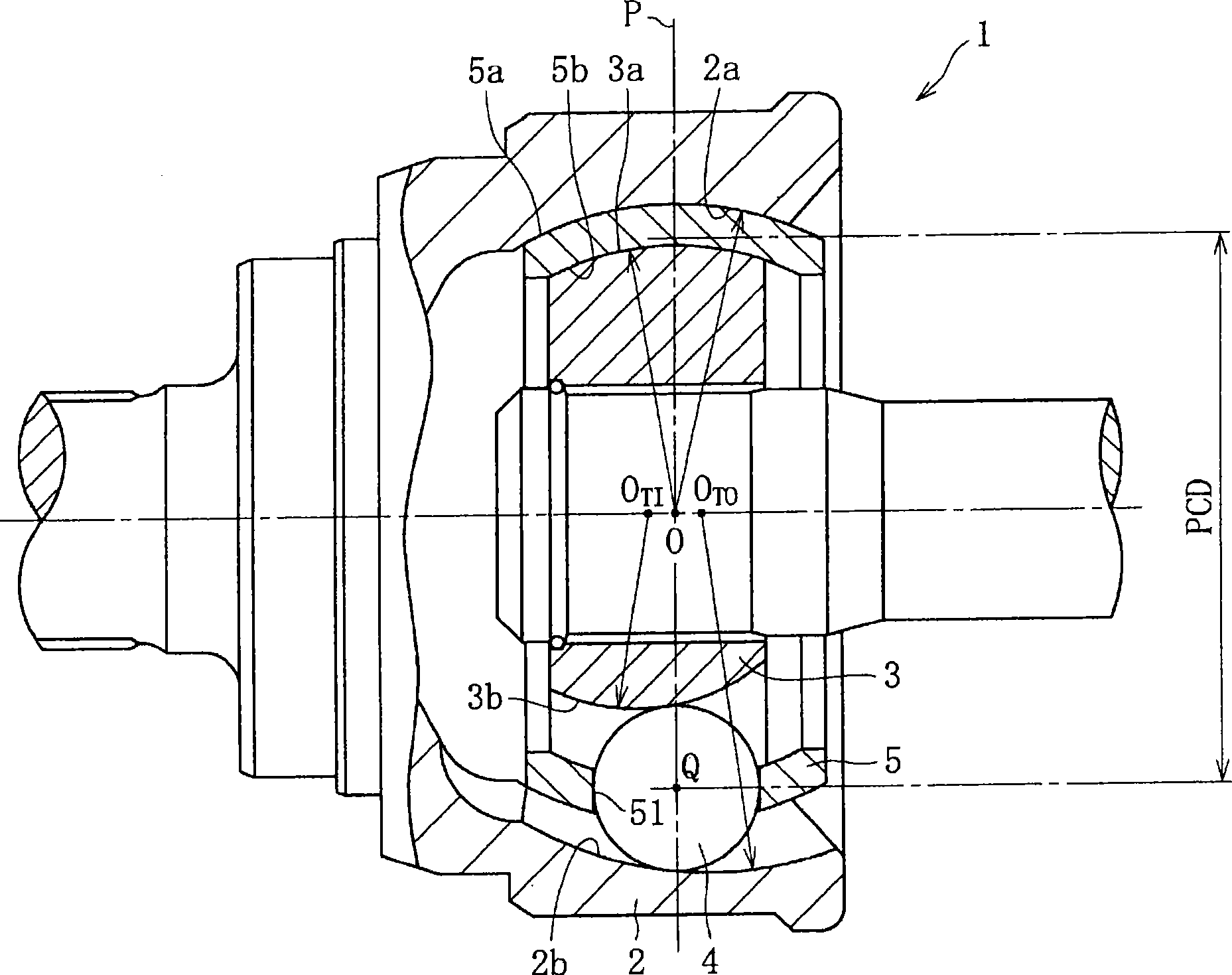
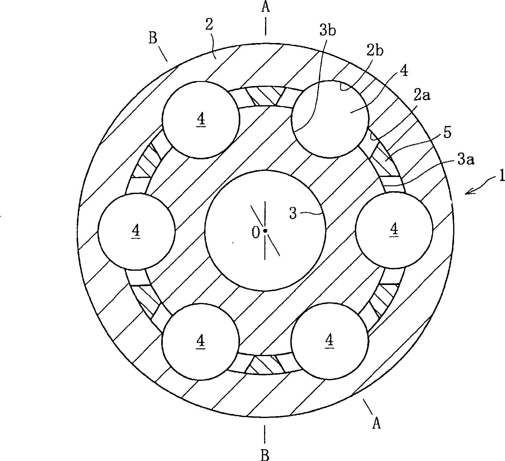
[0048] Such as Figure 1 ~ Figure 3 As shown, the constant velocity universal joint 1 of this embodiment includes: an outer member 2 (outer ring), an inner member 3 (inner ring), torque transmission balls 4 and a cage 5, wherein the outer member 2 is spherical A plurality of (usually 6) curved guide grooves 2b are formed along the axial direction on the inner peripheral surface 2a, and a plurality of (usually 6) curved guide grooves 2b are formed on the spherical outer peripheral surface 3a of the inner member 3 along the axial direction. ) Curved guide grooves 3b, and the torque transmission balls 4 are respectively disposed on the raceways formed by the cooperation of the guide grooves 2b of the outer member 2 and the guide grooves 3b of the inner member 3, and the cage 5 holds the torque transmission balls 4.

[0049] Center O of guide groove 2b of outer p...


PUM


Abstract

The invention provides a small-sized constant velocity universal joint having high strength and excellent operability and durability. The constant velocity universal joint satisfies the expression of 11.0 DEG <= phiT <= 15.0 DEG, where phiT is an offset angle formed by the center OTO of curvature of a guide groove (2b) of an outer member (2), the point Q at which a plane P of the joint and PCD cross, and the center OTI of curvature of a guide groove (3b) of an inner member (3).

Description

technical field [0001] The present invention relates to a constant velocity universal joint used in power transmission systems of automobiles and various industrial machines. Among the constant velocity universal joints that transmit torque smoothly at all times, the so-called fixed constant velocity universal joints do not slip (pitch) in the axial direction. Background technique [0002] like figure 2 and image 3 As shown, a BJ (ball joint) 1 used for a drive shaft of an automobile or the like is composed of an outer ring 2 , an inner ring 3 , torque transmission balls 4 , and a cage 5 . A cage 5 is provided between the outer ring 2 and the inner ring 3, and the cage 5 is in spherical contact with the spherical inner peripheral surface 2a of the outer ring 2 and the spherical outer peripheral surface 3a of the inner ring 3 respectively (for example, refer to Patent Document 1). . [0003] A plurality of curved guide grooves 2b, 3b are respectively formed on the inner ...

Claims


Application Information

Patent Timeline
Patent Type & Authority Applications(China)
IPC IPC(8): F16D3/224F16D3/223F16D3/2237F16D3/2245
CPCF16D2300/10F16D3/2245F16D3/223F16D3/2237F16D2003/22303F16D2250/00
Inventor 吉田和彦小林正纯东和弘
Owner NTN CORP
Why Eureka
Try Eureka