Die capable of continuously punching long screws

A long screw and mold technology, applied in forming tools, manufacturing tools, metal processing equipment, etc., can solve the problems of difficult guarantee, bending round bars, increasing energy consumption, etc., to achieve a convenient demoulding process, and avoid bending round bars. , the effect of improving work efficiency

Active Publication Date: 2014-01-08
JIANGSU HAOJIA STAINLESS STEEL STANDARD PARTS
View PDF6 Cites 6 Cited by
  • Summary
  • Abstract
  • Description
  • Claims
  • Application Information

AI Technical Summary

Problems solved by technology

[0003] The prior art dies for punching long screws have the following defects: First, since the round bar needs to be placed between the upper and lower dies, it is necessary to require that the distance between the upper and lower dies must be greater than that of the round bar when the die is opened. The length of the round rod is relatively large, generally more than 15cm, which will not only lead to a larger stroke of the upper mold, but also make the opening and closing of the mold take a long time and consume a lot of energy, and more importantly, the stroke of the upper mold will be larger. , that is, the larger the stroke, the more difficult it is to ensure that the upper mold is facing the round bar when the mold is closed, and it is easy to bend the round bar during stamping, resulting in a high scrap rate; secondly, each time a long screw is stamped, it needs to be opened and loaded separately 1. Stamping mold clamping, mold opening, demoulding five steps, how many screws need to be punched, the above five steps need to be repeated as many times, the speed is slow, the efficiency is low, and continuous stamping cannot be formed; again, the demoulding process is very inconvenient, Generally, it is necessary to install a jacking device at the bottom of the lower mold cavity of the lower mold. The jacking device will inevitably increase energy consumption, and even if there is a jacking device to loosen the long screws formed by stamping, workers still need to remove the long screws from the bottom of the lower mold. The lower mold cavity is dug out, so it is still inconvenient, and the speed is slow and the efficiency is low

Method used


Image

  • Die capable of continuously punching long screws
  • Die capable of continuously punching long screws
  • Die capable of continuously punching long screws

Examples


Embodiment Construction

[0016] The present invention will be further described below in conjunction with the drawings and specific embodiments.

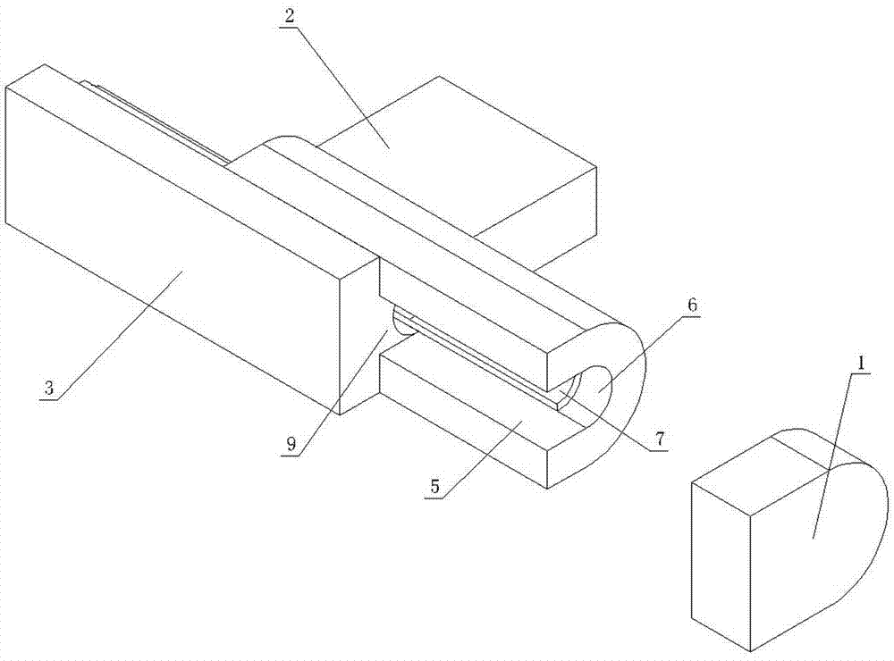
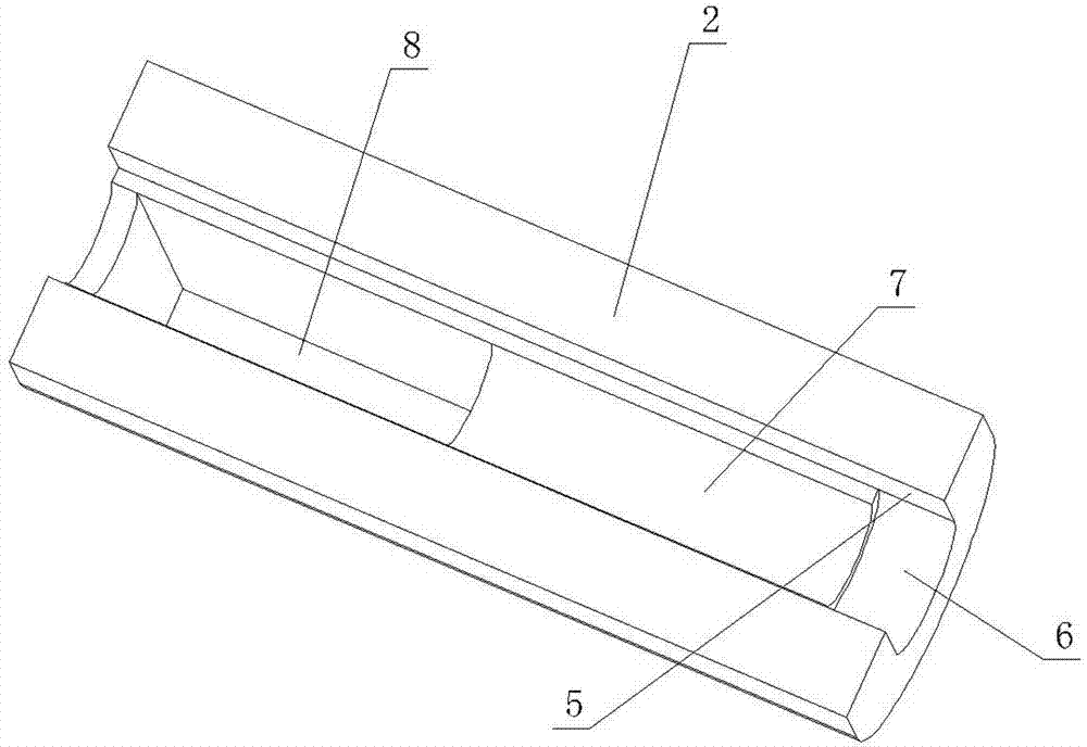
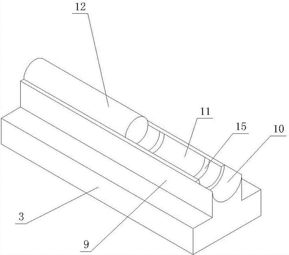
[0017] Such as figure 1 , figure 2 , image 3 , Figure 4 , Figure 5 As shown, the mold for continuous punching of long screws of the present invention includes a front punch 1, an upper mold shell 2 and a lower mold shell 3. The rear end surface of the front punch 1 is provided with an inner hexagonal protrusion 4, namely a hexagonal prism protrusion. The bottom surface of the upper mold shell 2 is provided with a guide groove 5 passing through the upper mold shell 2 along the length direction. The top of the guide groove 5 is sequentially provided with a first upper semicircular arc groove 6 and a second upper semicircular arc groove 7 from front to back. . The two upper semi-circular arc grooves are connected and concentric, and the term “concentric” means that the axes of the two upper semi-circular arc grooves are on the same straight line. The diame...


PUM


Abstract

The invention discloses a die capable of continuously punching long screws. The die comprises a front punch (1), an upper die casing (2) and a lower die casing (3). A guide groove penetrating through the upper die casing (2) is arranged on the upper die casing (2), the guide groove is provided with a first upper semicircle groove (6) and a second upper semicircle groove (7), a vertical blanking channel (8) is formed in the upper die casing (2), the lower die casing (3) is provided with a guide protruded stripe, the guide protruded stripe is provided with a first lower semicircle groove (10) and a second lower semicircle groove (11), a long screw head cavity (13) is formed by the first upper semicircle groove (6), the first lower semicircle groove (10), a rear end face of the front punch (1) and an inner hexagonal protrusion (4), and a long screw rod cavity (14) is formed by the second upper semicircle groove (7), a second lower semicircle groove (11) and a blocking column (12). The die is short in die opening and closing stroke, prevents a round bar used for punching the long screws from being bent in a punching process, is high in speed, is high in efficiency and is convenient to demould.

Description

Technical field [0001] The invention relates to the technical field of moulds, in particular to a mould for continuously stamping long screws. Background technique [0002] In the industry, screws with a length of more than 15 cm are generally called long screws. The traditional mold for punching long screws includes a lower mold and an upper mold. The upper end of the lower mold is provided with a blind hole that matches the shape of the screw, that is, the lower cavity, and the lower end of the upper mold is provided with a cylindrical recess. The top of the pit is provided with a hexagonal prism protrusion, and the cavity between the cylindrical pit and the hexagonal prism protrusion constitutes an upper mold cavity that matches the shape of the head of the hexagon socket screw, and the center lines of the upper and lower mold cavities coincide. Fix the lower mold, and put a round rod into the lower mold cavity. The length of the round rod is greater than the height of the lo...

Claims


Application Information

Patent Timeline
Patent Type & Authority Applications(China)
IPC IPC(8): B21D37/10B21D45/06
Inventor 陆昱森
Owner JIANGSU HAOJIA STAINLESS STEEL STANDARD PARTS
Why Eureka
Try Eureka