A tool used to limit the degree of freedom of workpiece rotation

A technology of degrees of freedom and workpieces, applied in the direction of manufacturing tools, metal processing machinery parts, positioning devices, etc., can solve problems such as prolonging the processing cycle, affecting the processing process, and scrapping the processed workpiece, so as to prevent rotation, ensure processing progress and processing accuracy Effect

Inactive Publication Date: 2016-06-08
浙江嵘翔机械制造有限公司
View PDF5 Cites 0 Cited by
  • Summary
  • Abstract
  • Description
  • Claims
  • Application Information

AI Technical Summary

Problems solved by technology

[0004] However, in the clamping method of the above-mentioned workpiece, the wheel hub or the main cabin is pressed tightly on the processing platform through the pressing block, and the rotation of the workpiece on the processing platform is only prevented by the contact between the workpiece and the processing platform and the workpiece and the pressing block. It is achieved by friction force. When the machine tool has a large processing force on the workpiece, the workpiece clamped on the processing platform is easy to rotate on the processing platform, which will seriously affect the processing process and prolong the processing cycle; if this situation If it is not discovered in time, it may also cause the scrapping of the processed workpiece and cause large economic losses

Method used


Image

  • A tool used to limit the degree of freedom of workpiece rotation
  • A tool used to limit the degree of freedom of workpiece rotation
  • A tool used to limit the degree of freedom of workpiece rotation

Examples


Embodiment Construction

[0024] The core of the present invention is to provide a tool for limiting the rotational freedom of the workpiece, so as to limit the rotational freedom of the large multi-angle workpiece, prevent the workpiece from rotating on the processing platform, and ensure the machining accuracy of the workpiece.

[0025] In order to enable those skilled in the art to better understand the solution of the present invention, the present invention will be further described in detail below in conjunction with the accompanying drawings and specific embodiments.

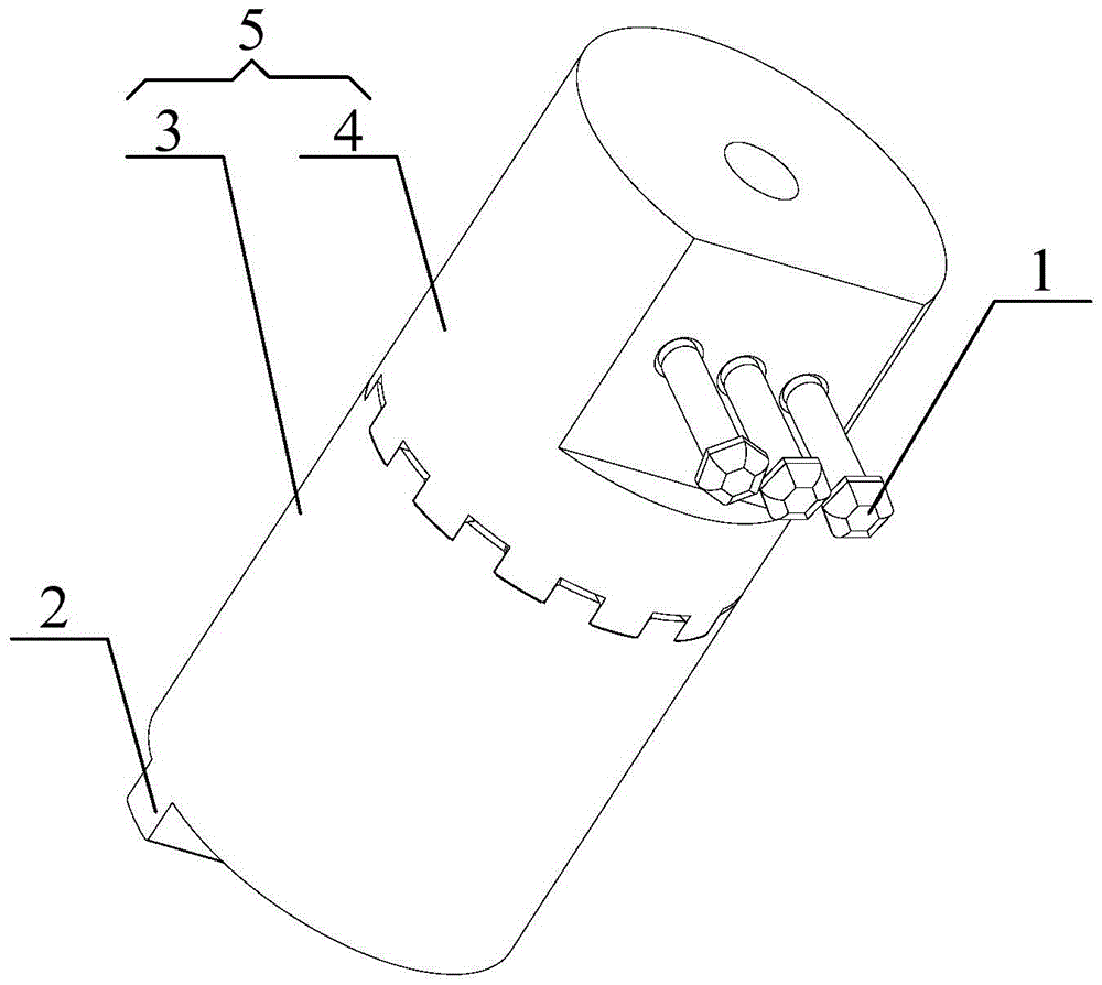
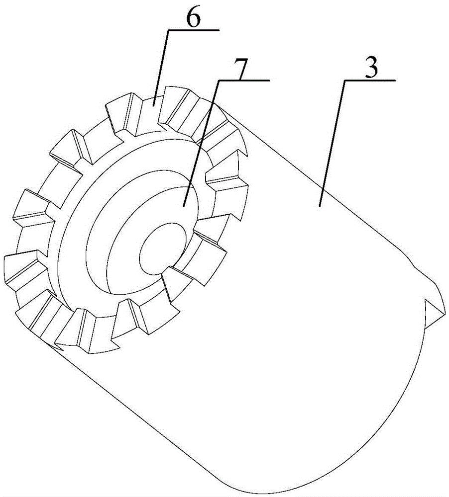
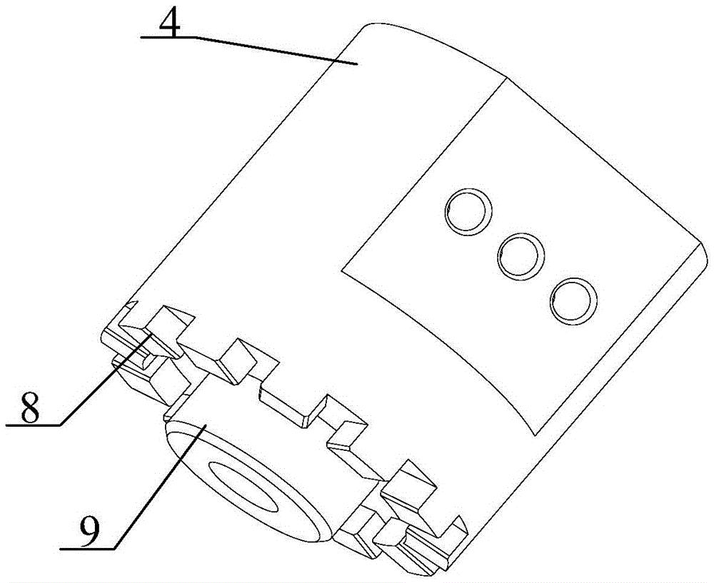
[0026] Please also refer to Figure 1 to Figure 3 , figure 1 It is an overall schematic diagram of the tooling used to limit the rotational freedom of the workpiece provided by the embodiment of the present invention, figure 2 Schematic diagram of the structure of the lower column provided by the embodiment of the present invention, image 3 It is a schematic diagram of the structure of the upper column provided by the embodime...


PUM


Abstract

The invention relates to a tool for limiting the rotating freedom degree of a workpiece. The tool for limiting the rotating freedom degree of the workpiece comprises a supporting pillar body and cap pillars, wherein a mounting part capable of being reliably fixed on a machining platform is arranged at one end of the supporting pillar body, and the cap pillars are arranged at the other end of the supporting pillar body and are used for abutting against the surface of the workpiece to be machined. When the workpiece in tight contact with the cap pillars has rotating tendency, the cap pillars supply acting force which is parallel to the machining platform and opposite to the rotating tendency of the workpiece to prevent the workpiece from rotating, and the cap pillars can be reliably supported by the supporting pillar body. Compared with the mode that the workpiece is prevented from rotating through friction force in the prior art, the supporting capability of the cap pillars in the tool to the workpiece is much larger that the friction force between the workpiece and a press block and the friction force between the workpiece and the machining platform, therefore, the workpiece pressed on the machining platform tightly can be effectively prevented from rotating in the machining process, and the machining progress and the machining precision of the workpiece are ensured.

Description

technical field [0001] The invention relates to the technical field of mechanical processing equipment, and more specifically relates to a tool for limiting the degree of freedom of rotation of a workpiece. Background technique [0002] During the processing of large multi-angle products, the positioning of the workpiece is a big problem. Since the general shape of large multi-angle products is multi-angle, multi-curved, and the shape is very irregular, the degree of freedom of rotation is very different during the clamping process. Easy to limit. [0003] Taking the hub and the main cabin, the main parts of the wind turbine as an example, the size of the hub and the main cabin of the wind turbine is very large, and the shapes of these two products are both multi-angle and multi-curved irregular shapes. At present, the clamping of the wheel hub and the main engine compartment is mainly to press the wheel hub and the main engine compartment on the processing platform through...

Claims


Application Information

Patent Timeline
Patent Type & Authority Patents(China)
IPC IPC(8): B23Q3/18
CPCB23Q3/062
Inventor 郑国陈伟唐树江吴水林
Owner 浙江嵘翔机械制造有限公司
Why Eureka
Try Eureka