
Installation device of counter bore gland of guide rail

A technology of installer and counterbore, which is applied in the field of guide rail counterbore gland installer, which can solve the problems that the gland is easy to be shaken or pressed over the plane of the guide rail, enters the slider, and affects the reliability or life of the guide rail pair.

Inactive Publication Date: 2014-01-08
NANJING TECHN EQUIP MFG
View PDF8 Cites 2 Cited by
  • Summary
  • Abstract
  • Description
  • Claims
  • Application Information

AI Technical Summary

Problems solved by technology

Because this method is more affected by human factors, the gland is easy to be shaken or pressed over the plane of the guide rail during installation, resulting in the gland being unable to be leveled on the upper plane of the guide rail. In addition, if the hammer is struck too hard, the surface of the guide rail will be damaged.
Because when the gland is not connected to the upper surface of the guide rail, these unconnected places become blind spots for the sealing and scraping of the guide rail pair, and dirt or iron pins and other stains in daily work will accumulate in these places, thus there will be It may enter the inside of the slider and affect the reliability or life of the guide rail pair

Method used


Image

  • Installation device of counter bore gland of guide rail
  • Installation device of counter bore gland of guide rail
  • Installation device of counter bore gland of guide rail

Examples


Embodiment Construction

[0013] The present invention will be further described below in conjunction with the accompanying drawings and specific embodiments.

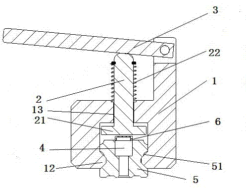
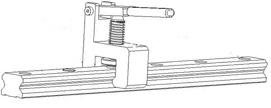
[0014] The guide rail counterbore gland installer includes a frame 1, a pressing bar 2 and a handle 3, two vertical sides of the guide rail are symmetrically provided with chute 51, counterbore holes 4 are evenly arranged on the guide rail 5, and the frame 1 The lower part is symmetrically arranged with a V-shaped slider 12, and the slider 12 is placed in the chute 11 so that the frame 1 is horizontally slid on the guide rail 5; the middle part of the frame 1 is provided with a guide hole 13, and the pressure rod 2 passes through the guide The hole 13 is slidably arranged on the frame 1 up and down, and the lower end of the pressing rod 2 is provided with a pressing plate 21 opposite to the counterbore 4 . One end of the handle 3 is hinged with the top of the frame 1, and the middle part is hinged with the upper end of the depression bar 2. A ...


PUM


Abstract

The invention relates to an installation device of a counter bore gland of a guide rail. The installation device of the counter bore gland of the guide rail comprises a machine frame, a pressing rod and a handle, wherein the machine frame is arranged on the guide rail and can slide on the guide rail horizontally, the pressing rod is arranged on the machine frame and can slide vertically on the machine frame, one end of the handle is hinged to the upper portion of the machine frame, and the middle of the handle is hinged to the upper end of the pressing rod. According to the installation device of the counter bore gland of the guide rail, the lever principle is adopted, the gland is pressed into a counter bore through the pressing rod with relatively even force and speed, damage, caused by impact to the upper surface of the guide rail, of the guide rail is avoided, and the gland can be attached to the upper surface of the guide rail more smoothly.

Description

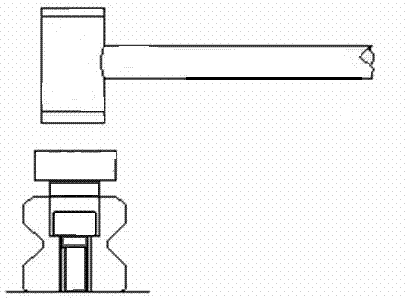
technical field [0001] The invention relates to a guide rail counterbore gland installer. Background technique [0002] Traditional gland installation methods such as figure 1 As shown, put the gland on the counterbore of the guide rail, place a flat metal sheet on the gland, and hit it with a hammer to knock the gland into the counterbore. Because this method is more affected by human factors, the gland is easily tilted or pressed over the plane of the guide rail during installation, resulting in the gland being unable to be leveled on the upper plane of the guide rail. In addition, if the hammer is struck too hard, the surface of the guide rail will be damaged. . Because when the plane of the gland on the guide rail is not connected, these unconnected places become blind spots for the sealing and scraping of the guide rail pair, and dirt or iron pins and other stains in daily work will accumulate in these places, thus there will be It may enter the inside of the slider ...

Claims


Application Information

Patent Timeline
IPC IPC(8): B25B27/02
CPCB25B27/02
Inventor 殷玲香王守珏陈学勇纪明民张怀燕
Owner NANJING TECHN EQUIP MFG
Learn More