Indoor load test device for post-grouting of pile ends

A load test and post-grouting technology, which is applied in the preparation of test samples and the use of stable tension/pressure to test the strength of materials, etc., to achieve the effects of ensuring stability and firmness, convenient installation and operation, and a wide range of applications

Inactive Publication Date: 2016-11-02
ZHEJIANG IND POLYTECHNIC COLLEGE
View PDF8 Cites 0 Cited by
  • Summary
  • Abstract
  • Description
  • Claims
  • Application Information

AI Technical Summary

Problems solved by technology

[0003] Aiming at the problems of the current pile static load test, the present invention proposes an indoor load test device capable of carrying out the static load test of post-grouting of pile ends indoors

Method used


Image

  • Indoor load test device for post-grouting of pile ends
  • Indoor load test device for post-grouting of pile ends
  • Indoor load test device for post-grouting of pile ends

Examples


Embodiment 1

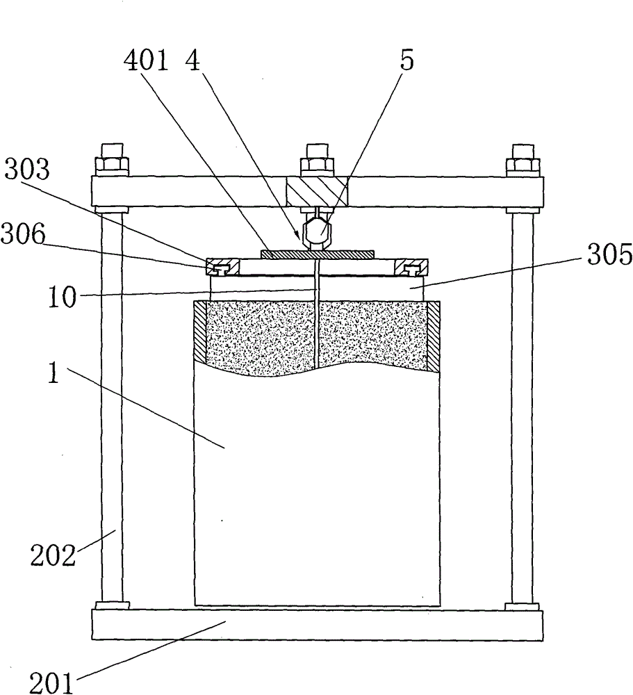
[0056] refer to Figure 1 to Figure 4 , the load test device in the post grouting chamber of the pile end includes a load box 1, a counter force device 2, a soil pressurization device 3, and a pile body pressurization device 4.

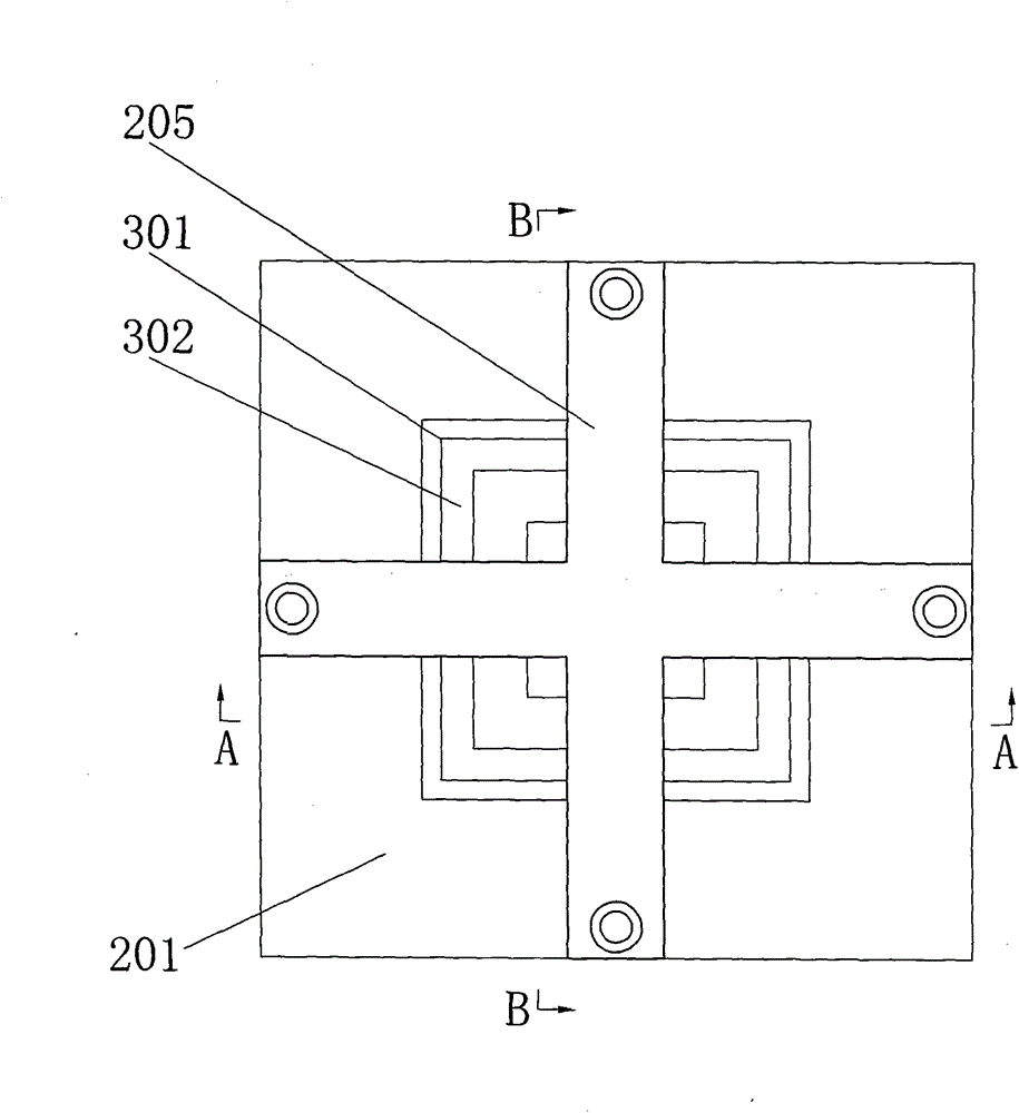
[0057] The reaction force device 2 in the present invention includes a chassis 201 , four connecting rods 202 , a reaction force frame 203 and an adjustment structure 204 . The reaction force frame 203 includes two reaction force rods 205 arranged in a cross shape and fixed in the middle. The reaction force rods 205 have two parallel upper and lower planes, and two ends of each reaction force rod 205 are respectively provided with a through The through holes 206 on the upper and lower planes. The lower ends of the four connecting rods 202 are provided with external threads 209, and are fixedly connected to the chassis 201 by nuts 210; the upper ends of the four connecting rods 202 are connected with the reaction force frame 203 through the adjustment...

Embodiment 2

[0067] refer to Figure 5 with Image 6 As shown, the difference between this embodiment and Embodiment 1 is that the adjusting bolt 207 includes a connecting head 20a and a positioning ring 20h, the connecting head 20a has a ring-shaped connecting portion 20c and a clamping portion 20e, and the internal threaded hole 208 runs through The connecting part 20c and the clamping part 20e; the clamping part 20e is located at one end of the connecting part 20c and protrudes radially outward, and the positioning ring 20h is clamped at the other end of the connecting part 20c. Specifically: the outer surface of the annular connecting portion 20c is provided with two guide grooves 20j along the axial direction and two annular grooves 20k extending along the same circumferential direction of the connecting portion 20c, one guide groove 20j communicates with one annular groove 20k The inside of the positioning ring 20h has two positioning blocks 20i protruding inward. When the positioni...

Embodiment 3

[0069] The test method of the post-grouting indoor load test device at the pile end is an indoor pile static load simulation test. This test method includes the following steps:

[0070] The first step is to make the pile body 10 . Make the pile body 10 forming mold first: take one or more hollow round steel pipes whose length is longer than the pile body 10, cut the round steel pipes into two semi-arc or three arc-shaped arc petals along the axis direction; buckle the arc petals into A round steel pipe, and the two ends and the middle of the round steel pipe are fastened by ring screws; one end of the round steel pipe is sealed, and a layer of cotton gauze is placed inside the end, and the other end is an open end. Make the pile body 10 reinforcement structure: select the thin steel bar to make it into a reinforcement cage that can be put into the round steel pipe; place the round steel pipe vertically with the open end up; put the reinforcement cage into the round steel pipe...


PUM


Abstract

The invention relates to a load test device and a test method in a grouting chamber after a pile end. The device includes a load box, a reaction device, a soil pressure device, and a pile pressure device; the reaction device includes a chassis, a connecting rod and a reaction frame ; The lower end of the connecting rod is fixedly connected to the chassis, and the upper end of the connecting rod is connected to the reaction frame, and an adjustment structure for adjusting the height of the reaction frame is provided between the connecting rod and the reaction frame; the load box is arranged on the chassis, and the soil The body pressurizing device and the pile body pressurizing device are both arranged between the load box and the reaction frame; the method includes making the pile body, filling soil in the load box, positioning the pile body, setting slurry bubbles, pressurizing the soil body, and Body pressurization and other steps. The disclosure of the device and method overcomes the traditional problem that the post-grouting indoor load test of pile ends cannot be performed indoors. And it produces the following beneficial effects: it can simulate the force condition and bearing mechanism of the grouting group piles in the indoor experiment, and can simulate single piles and pile groups, piles of different depths and different distances, and has strong adaptability and multiple functions.

Description

technical field [0001] The invention relates to an indoor load test suitable for pile end post grouting, in particular to an indoor load test device for pile end post grouting. Background technique [0002] With the vigorous development of the construction industry, bored cast-in-place piles have been widely used in the construction industry due to their convenient construction. type of use function. In the 1960s, the post-grouting process appeared in the pile end and pile side of the pile type, which made up for the insufficient bearing capacity of the pile type, and the application of this technology has been recognized by geotechnical engineering. However, due to the relatively short rise time of this technology, although many experiments have been done in actual engineering and some progress has been made, many theories are still far from perfect, especially in the load test. On the one hand, because the test conditions are not available in the project, only the static...

Claims


Application Information

Patent Timeline
Patent Type & Authority Patents(China)
IPC IPC(8): G01N3/08G01N1/28
Inventor 林群仙李少和黄曼周立强周明荣
Owner ZHEJIANG IND POLYTECHNIC COLLEGE
Why Eureka
Try Eureka