fuel dispenser

A technology of fuel distributor and fuel distribution, which is applied in the direction of low-pressure fuel injection, low-pressure fuel injection, fuel injection device, etc., and can solve problems such as application range limitation

Inactive Publication Date: 2017-08-15
ROBERT BOSCH GMBH
View PDF10 Cites 0 Cited by
  • Summary
  • Abstract
  • Description
  • Claims
  • Application Information

AI Technical Summary

Problems solved by technology

However, the range of application of such fuel distributor strips for low pressure applications is limited to the low pressure range

Method used


Image

  • fuel dispenser
  • fuel dispenser

Examples


Embodiment Construction

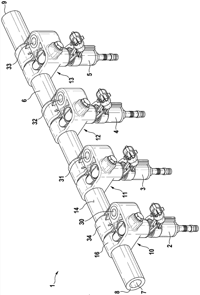
[0017] figure 1 A schematic perspective view of a fuel distributor 1 according to one embodiment of the invention is shown. Furthermore, fuel injection valves 2 , 3 , 4 , 5 mounted on fuel distributor 1 are shown. The fuel distributor 1 can in particular be designed in the form of a fuel distributor strip 1 . The fuel distributor 1 is particularly suitable for externally ignited internal combustion engines which compress the mixture. Here, the fuel distributor 1 is particularly suitable for medium-pressure systems. Here, the medium pressure for such a medium pressure system may be in the range of 3 MPa to 10 MPa or 30 bar to 100 bar. In particular, the medium pressure may be in the range of 5Mpa to 7Mpa or 50bar to 70bar. However, the fuel distributor 1 according to the invention is also suitable for other applications.

[0018] The fuel distributor 1 has a distributor body 6 . The distributor body 6 is designed as a tubular distributor body 6 in the present exemplary em...


PUM


Abstract

A fuel distributor (1), in particular for a compressed mixture, externally ignited internal combustion engine, said fuel distributor comprising a distributor body (6) and at least one sleeve (10), said sleeve being at least Constructed on a plastic base piece. A fuel chamber (7) is formed in the distributor body (6). Furthermore, a through channel (20) is provided on the distributor body (6) in the region of the sleeve (10), which opens on one side into the fuel chamber of the distributor body (6) (7) and open on the other side into the inner chamber (21) of the sleeve (10). The sleeve (10) has a sealing lip (22), wherein the through channel (20) opens into the interior of the sleeve (10) at a central opening (24) of the sealing lip (22). room (21).

Description

technical field [0001] The invention relates to a fuel distributor, in particular for mixture-compressing, externally ignited internal combustion engines. In particular, the invention relates to the field of fuel injection devices configured as medium-pressure systems. Background technique [0002] In fuel injection systems for motor vehicles, it is conceivable to use fuel distribution rails which, for high-pressure applications, consist of steel or aluminum. Thus, pressure strengths for pressures greater than 15 MPa (150 bar) can be achieved. Such a high-pressure rail made of steel can be produced as a welded rail. Here, a steel pipe is used as the base part, on which the individual components, in particular the closing cap, the screw holder, the high-pressure connection and the connection for the injection valve, are welded. However, this configuration is associated with high manufacturing costs. [0003] Furthermore, a fuel distributor strip for low pressure applicati...

Claims


Application Information

Patent Timeline
Patent Type & Authority Patents(China)
IPC IPC(8): F02M55/02F02M69/46F02M55/00
CPCF02M55/025F02M55/005F02M69/465
Inventor M·法伊格尔H·乌里希N·豪特曼D·乌伦布洛克M·格纳
Owner ROBERT BOSCH GMBH
Why Eureka
Try Eureka