Refrigerant compressor

一种压缩机、制冷剂的技术,应用在机械设备、机器/发动机、液体变容式机械等方向,能够解决不经济、高加工费用、活塞加工耗费等问题,达到生产成本节省的效果

Active Publication Date: 2016-07-06
ACC AUSTRIA GMBH
View PDF7 Cites 0 Cited by
  • Summary
  • Abstract
  • Description
  • Claims
  • Application Information

AI Technical Summary

Problems solved by technology

However, the machining of pistons of different sizes and diameters required here is complex and uneconomical
The precise final machining of the reamed piston bore in the region of the piston running surface also results in high machining costs

Method used


Image

  • Refrigerant compressor
  • Refrigerant compressor
  • Refrigerant compressor

Examples


Embodiment Construction

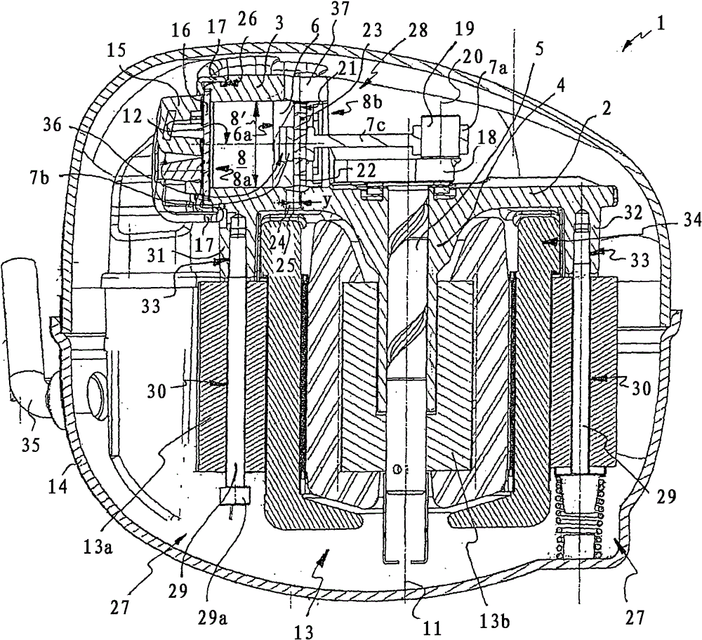
[0042] figure 1 A refrigerant compressor according to the invention is shown comprising a hermetically sealed compressor housing 14 . Arranged in the compressor housing 14 is an electric motor 13 , which is supported in the bottom region of the compressor housing 14 by means of an elastic bearing.

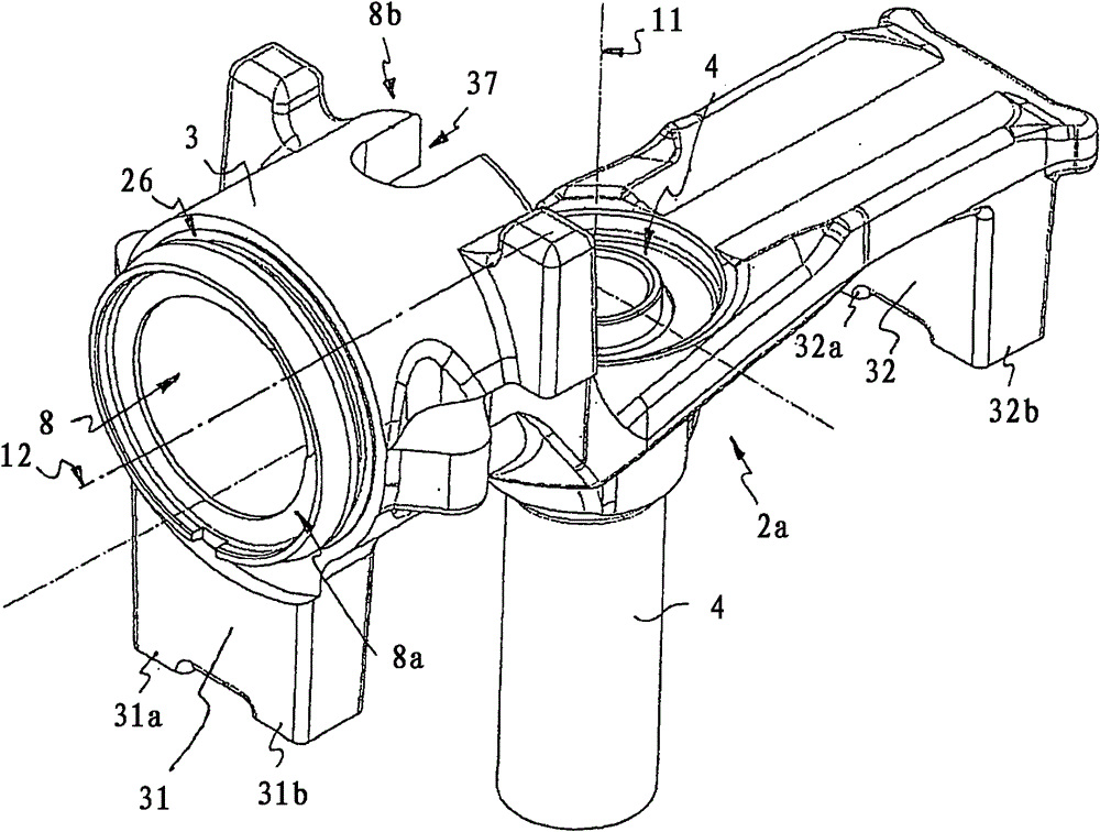
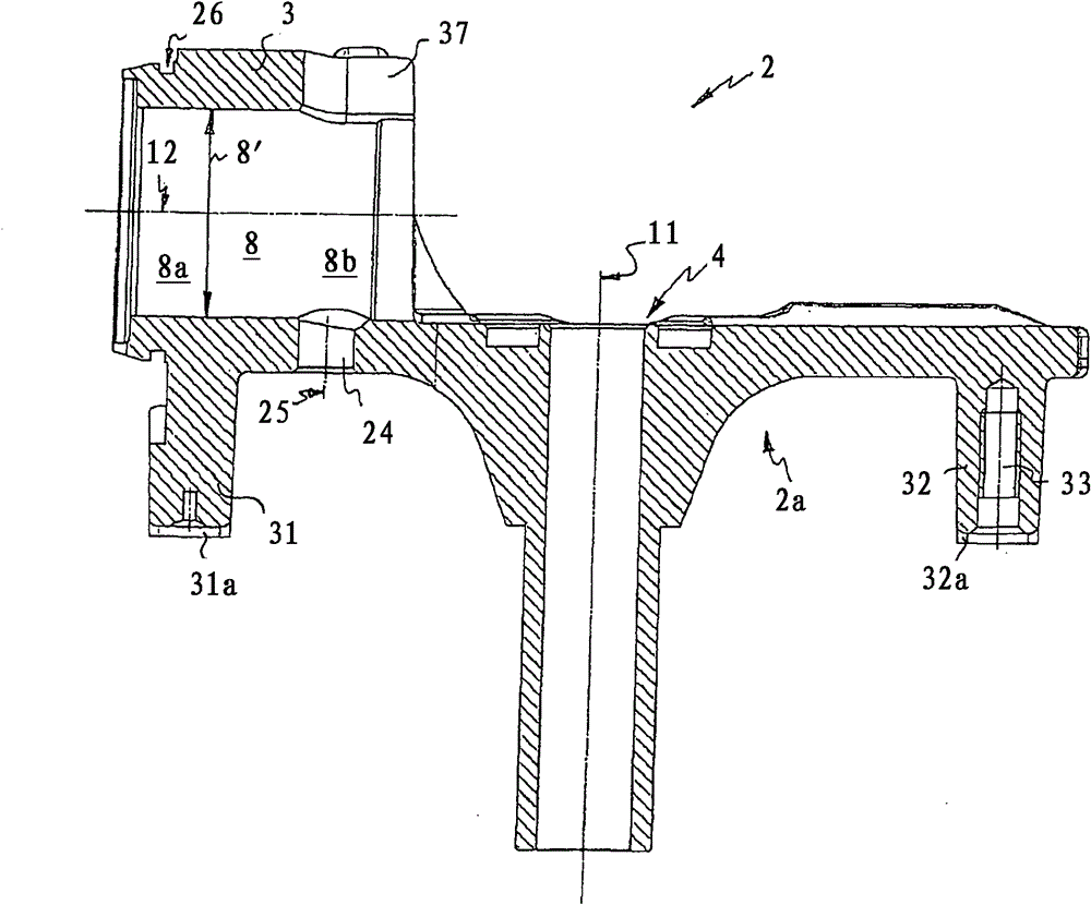
[0043] Mounted on the electric motor 13 is a bridge-shaped support body 2 , which is fastened to the stator 13 a of the electric motor 13 by means of screw elements 29 . exist figure 2 The support body 2 , shown in detail, spans the upper part of the motor winding 34 of the electric motor 13 (also referred to as “upper winding head”) and has two mutually opposite foot elements 31 and 32 , which are supported on the stator 13 a . Each foot element 31, 32 has two abutments 31a, 31b or 32a, 32b on the end faces, so that the support body 2, which is formed narrowly, is thus stably supported on the stator 13a on a total of four support surfaces (see press Figure 5 Bottom view of s...


PUM


Abstract

A hermetically encapsulated refrigerant compressor (1) comprising a cylinder housing (3) and a piston (6) guided along a defined piston working surface (9) in a piston bore (8) of the cylinder housing (3) for To compress the working medium, said piston is articulated by means of a connecting rod (7) on a crankshaft (5) driven by an electric motor (13), wherein the crankshaft (5) is supported on a support preferably formed in one piece with the cylinder housing (3) body (2), and the piston bore (8) is closed on a first end region (8a) by a cylinder head (15) including a valve plate (16), while the piston bore (8) is closed on a side facing the crankshaft The second end region (8b) of (5) is open in order to accommodate the piston (6); it is characterized in that the piston hole (8) has a connected on the piston working surface (9) facing the crankshaft (5) A void portion (10) is provided in the second end region (8b) of the piston hole (8), and the opening internal width (10′) of the void portion is greater than the diameter of the piston working surface (9) ( 9') in order to prevent contact between the piston (6) and the cylinder housing (3) in this section during the working position of the piston (6).

Description

technical field [0001] The invention relates to a hermetically packaged refrigerant compressor comprising a cylinder housing and a piston guided along a defined piston working surface in a piston bore of the cylinder housing for compressing a working medium, the cylinder housing being used as a The basis for the manufacture of various structural series of refrigerant compressors with working volumes of different sizes, said piston is articulated by means of a connecting rod on a crankshaft driven by an electric motor, wherein the crankshaft rotatable about a rotation axis is supported preferably in connection with the cylinder housing In a one-piece support body, the piston bore is closed on a first end region by a cylinder head comprising a valve plate, while the piston bore is open on a second end region facing the crankshaft for accommodating the piston, the piston bore has a free-running portion adjacent to the piston running surface, arranged in the region of the second e...

Claims


Application Information

Patent Timeline
Patent Type & Authority Patents(China)
IPC IPC(8): F04B39/12
CPCF04B39/121F04B39/122F04B2201/0206
Inventor W·布拉贝克A·施魏格霍费尔S·兰普雷希特
Owner ACC AUSTRIA GMBH
Why Eureka
Try Eureka