Mousetrap

A mousetrap and mousetrap technology, applied in the field of mousetrap devices, can solve the problems of single species of mousetrap and different mousetrap effects, and achieve the effect of light capture

Inactive Publication Date: 2014-01-15
刘大伟
View PDF0 Cites 7 Cited by
  • Summary
  • Abstract
  • Description
  • Claims
  • Application Information

AI Technical Summary

Problems solved by technology

[0002] There are only one type of mousetrap available in the market, and the mousetrap effects are also different.

Method used


Image

  • Mousetrap

Examples


Embodiment Construction

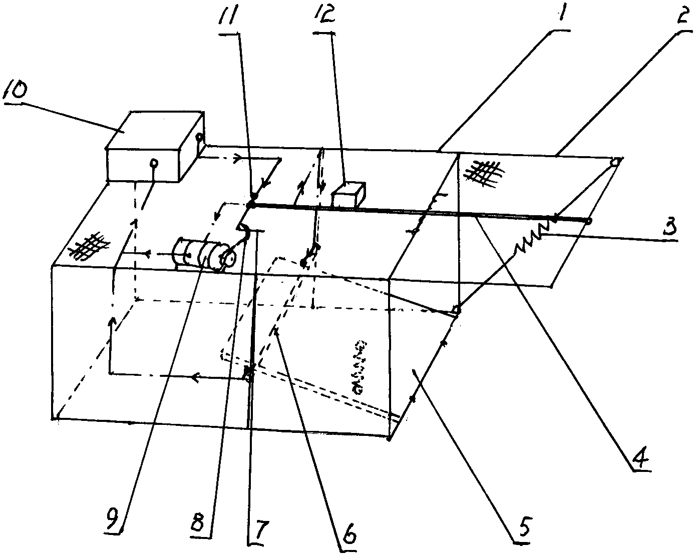
[0008] refer to figure 1 , the mousetrap is to establish a magnet piece 12 on the top surface of the mousetrap 1, and the magnet piece 12 sucks the cage door pull bar 4, and the front end of the cage door pull bar 4 is provided with a current contact and an elbow 7, and the elbow 7 U-shaped hook 8 is articulated on the top, and a stay rope is connected on the U-shaped hook 8, and the stay rope is wound on the transmission wheel of the micro motor 9. The micro motor 9 is driven by the battery in the battery box 10, and the battery box 10 leads The wire touches the cage door pull rod 4, then touches the metal rod 6 set under the mouse pedal 5 connected under the cage door, and finally returns to the battery box 10 to form a loop; the current contact of the cage door pull rod 4 is connected to the wire Be connected with micromotor 9, the circuit lead of micromotor 9 also returns to battery box 10; An extension spring 3 is arranged between.


PUM


Abstract

The invention relates to a mouse trapping device, in particular to a mousetrap. A magnet is arranged on the top face of a mouse trapping cage to attract a cage door pull rod, a current contact and a bend are arranged at the front end of the cage door pull rod, a U-shaped hook is hung on the bend and connected with a pull rope, and a micro motor is used for driving the pull rope. A metal rod arranged under a mouse pedal connected to a cage door can be connected with the current contact in a contact mode, the current contact on the cage door pull rod is connected with the micro motor through a connecting wire, a pushing spring is arranged between the lower face of the mouse pedal and the bottom face of the mouse trapping cage, and a tension spring is arranged between an upper corner and a lower corner of the cage door. The mousetrap has the advantages that all mouse trapping motions of the mousetrap are finished instantly, mice entering the cage can not run away, and the mousetrap can be used for trapping mice quickly and easily.

Description

Technical field: [0001] The invention relates to a mouse trap. Background technique: [0002] The kind of mousetrap supplied on the market is single, and the effect of catching mice is also varied. Therefore, many people are inventing the mousetrap that structure is simple and can improve mousetrap effect again. Invention content: [0003] The purpose of the present invention is to provide a mousetrap. The mousetrap is composed of a mousetrap cage, a magnet block, a cage door pull rod, a micro motor, a battery box, an extension spring, a U-shaped hook, a mouse pedal, and a top spring. The mousetrap of the mousetrap is provided with a magnet block, a cage door pull rod, a micro-shaped motor, a battery box, and a U-shaped hook, and a mouse pedal, a top spring, and a cage door extension spring are arranged in the mousetrap; the cage door pull rod and the U-shaped hook It is connected with the mouse pedal, the micro motor and the battery box with wires. Use the mousetrap t...

Claims


Application Information

Patent Timeline
Patent Type & Authority Applications(China)
IPC IPC(8): A01M23/10
Inventor 刘大伟
Owner 刘大伟
Why Eureka
Try Eureka