Portable electronic device

a technology of electronic devices and portable devices, applied in the field of electronic devices, can solve the problems of time-consuming calculation, inability to see where the user at the other end of the internet is moving, etc., and achieve the effect of quick rotation and quick capture of object images

Inactive Publication Date: 2010-01-28
ASUSTEK COMPUTER INC
View PDF9 Cites 19 Cited by
  • Summary
  • Abstract
  • Description
  • Claims
  • Application Information

AI Technical Summary

Benefits of technology

[0020]In the portable electronic device, the object-image capture module can quickly rotate or move in a mechanical manner to track the user. In addition, upon receiving a signal at the receiver, the control circuit controls the first transmission mechanism and the second transmission mechanism to drive the object-image capture module to rotate so as to automatically track the object whose image is to be captured. In comparison with the existing object tracking system using the image processing technology, the object-image capture module of the portable electronic device of the present invention can more quickly capture the object image.

Problems solved by technology

However, during the internet meeting, the user often needs to move, for example, to an adjacent position to fetch a document.
When the user moves out of the capture range of the capture lens, the user at the opposite end of the internet cannot see where the user at this one end is moving.
However, using the image processing application to drive the capture lens to move needs time for calculation.
When the user's hardware cannot meet the requirement of the calculation speed of the image processing application, at the time the image processing application needs for calculation may be very long which may lead to a lag.
As a result, the capture lens moves slowly which may not catch up with the user during the user's movement.

Method used


Image

  • Portable electronic device
  • Portable electronic device
  • Portable electronic device

Examples


first embodiment

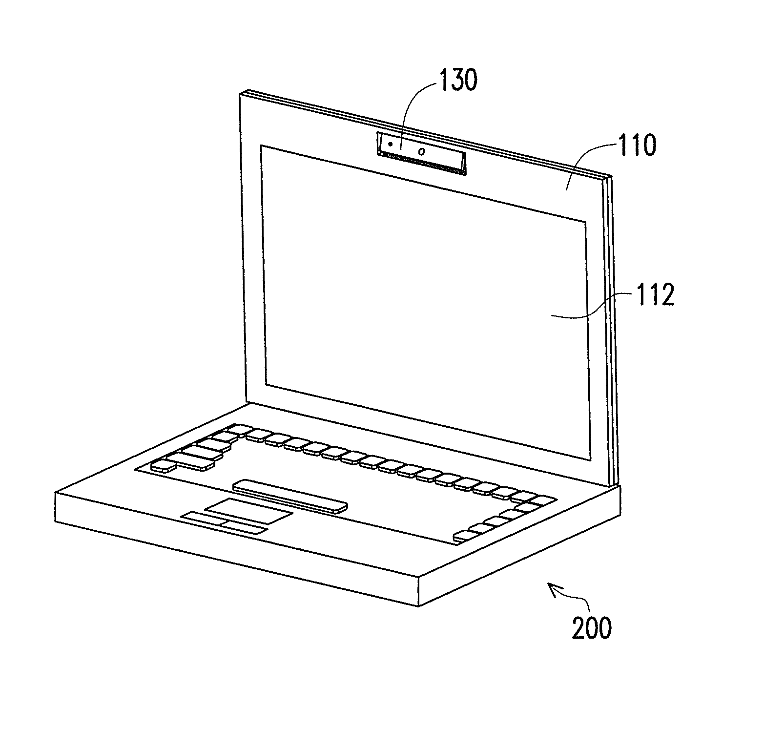
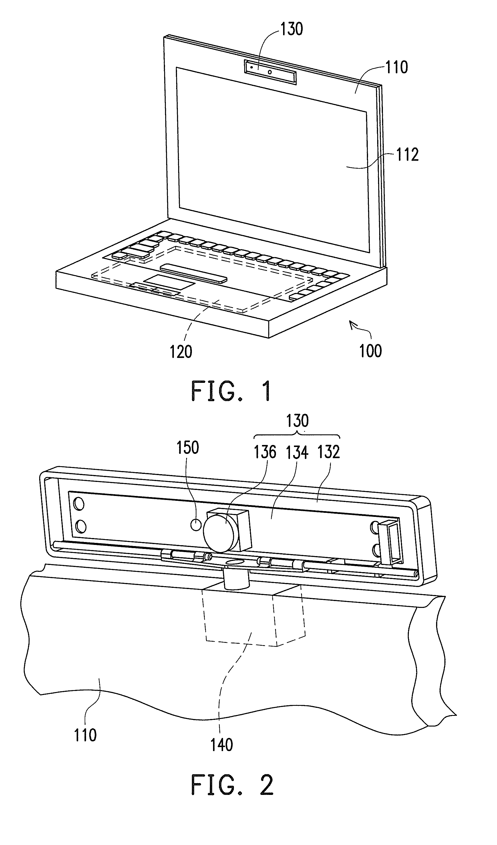
[0033]FIG. 1 illustrates a portable electronic device according to a first embodiment of the present invention. FIG. 2 illustrates the object-image capture module and the body of FIG. 1. Referring to FIGS. 1 and 2, the portable electronic device 100 includes a body 110, a control circuit 120, an object-image capture module 130, a first transmission mechanism 140, and a receiver 150. The body 110 is, for example, a notebook computer and includes a liquid crystal display 112. The control circuit 120 is disposed in the body 110 and electrically connected with the liquid crystal display 112.

[0034]The object-image capture module 130 independent of the body 110 is embedded into the body 110 and includes a housing 132, an object-image capture circuit 134, a base, and a lens 136. The object-image capture circuit 134 is electrically connected to the control circuit 120. The object-image capture circuit 134 and the base are both disposed in the housing 132. The lens 136 is electrically connec...

second embodiment

[0044]The present embodiment is similar to the first embodiment in which like reference numerals indicate like components. The explanation of those same components is not repeated and below description is made only with regard to components that are different.

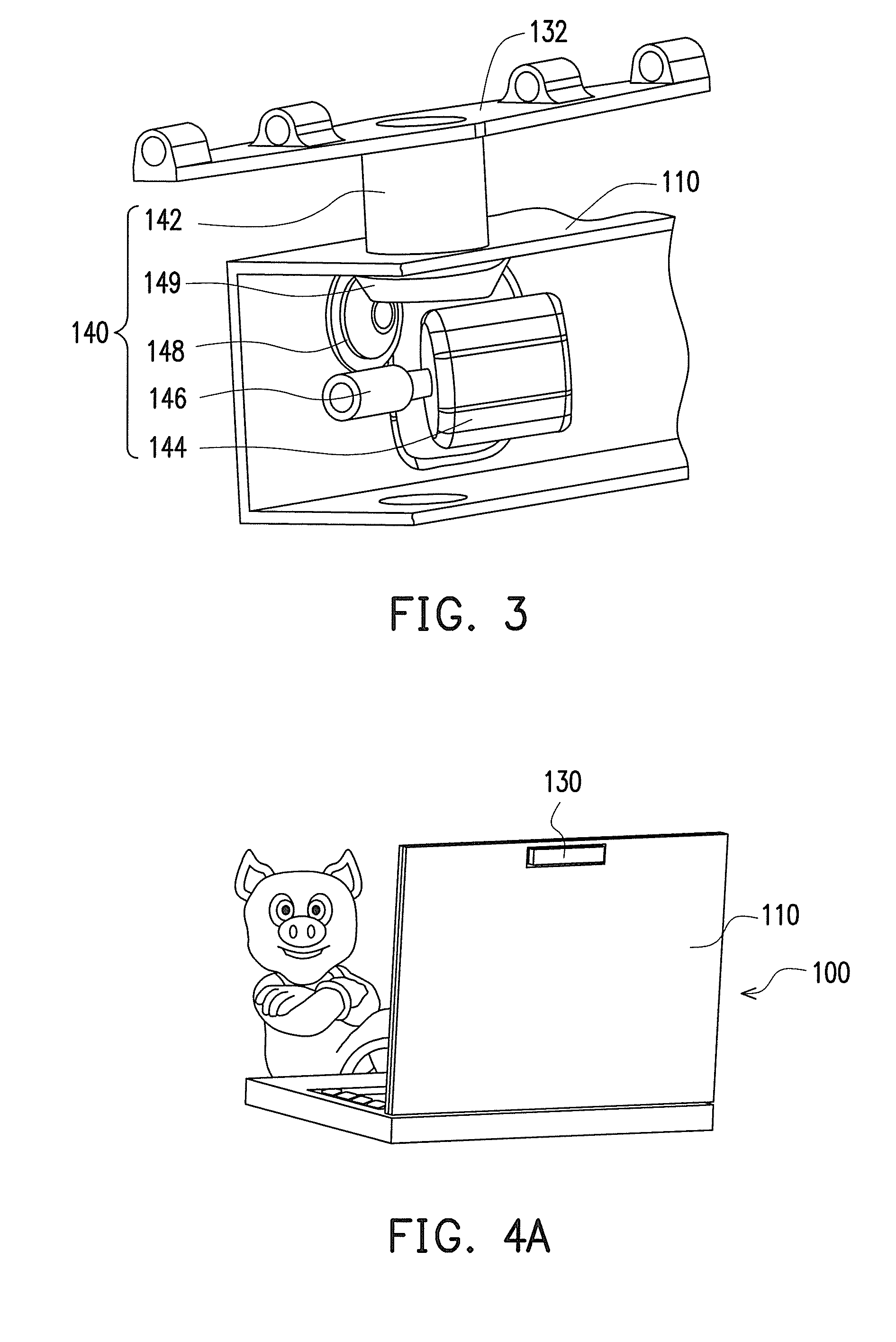
[0045]FIG. 5 illustrates the portable electronic device of FIG. 1 that uses another first transmission mechanism. Referring to FIG. 5, the first transmission mechanism 140′ of the present embodiment includes a first shaft 142, a stepper motor 144′, a first gear 146′, and a second gear 148′. The stepper motor 144′ and the first gear 146′ are disposed in the body 110. The first gear 146′ is connected with the stepper motor 144′. The second gear 148′ is also disposed in the body 110 and attached around the first shaft 142. The second gear 148′ is engaged with the first gear 146′.

[0046]When the user moves, the receiver 150 (shown in FIG. 2) receives a signal and transmits the signal to the control circuit 120 (shown in FIG. 1). The...

third embodiment

[0047]The present embodiment is similar to the first, second embodiments in which like reference numerals indicate like elements. Below description is made only with regard to the difference between the present embodiment and the first, second embodiments.

[0048]FIG. 6 illustrates a portable electronic device according to a third embodiment of the present invention, and FIG. 7 illustrates the object-image capture module and second transmission mechanism of the portable electronic device of FIG. 6. Referring to FIG. 6 and FIG. 7, different from the first and second embodiments, the portable electronic device 200 of the present embodiment employs a second transmission mechanism 260 to rotate the object-image capture module 130 upward or downward about a second shaft 262 of the second transmission mechanism 260. The second transmission mechanism 260 is disposed in the housing 132 adjacent to the lens 136. While the second transmission mechanism 260 is disposed in the housing 132 in the ...


PUM


Abstract

A portable electronic device including a body, a control circuit, an object-image capture module, a first transmission mechanism and a receiver is provided. The control circuit is disposed in the body. The object-image capture module independent of the body includes a housing, an object-image capture circuit and a lens. The object-image capture circuit is disposed in the housing, and the lens is electrically connected to the control circuit by the object-image capture circuit. The first transmission mechanism includes a first shaft connected between the body and the object-image capture module. The receiver is electrically connected to the control circuit. The receiver is used to receive a signal and transmit the signal to the control circuit, such that the control circuit controls the first transmission mechanism to drive the object-image capture module to rotate about the first shaft.

Description

CROSS-REFERENCE TO RELATED APPLICATION[0001]This application claims the priority benefit of Taiwan application serial no. 97127938, filed on Jul. 23, 2008. The entirety of the above-mentioned patent application is hereby incorporated by reference herein and made a part of specification.BACKGROUND OF THE INVENTION[0002]1. Field of the Invention[0003]The present invention generally relates to electronic devices, and more particularly, to a portable electronic device which is capable of automatically tracking a user.[0004]2. Description of Related Art[0005]The development in the internet and multimedia technology brings people far away from each other together. Users who get used to computers often use web cameras to talk to each other over a long distance, which we called “internet meeting”.[0006]The web camera is typically placed on a table and the user at one end sits in front of a capture lens of the web camera. The capture lens is oriented in a particular direction to capture imag...

Claims


Application Information

Patent Timeline
Patent Type & Authority Applications(United States)
IPC IPC(8): H04N5/225
CPCG03B17/00G06F1/1616H04N7/142H04N5/2251G06F1/1686H04N23/57
Inventor WANG, WEN-HUNGFANG, TZU-HAO
Owner ASUSTEK COMPUTER INC
Why Eureka
Try Eureka