Valves for beverage filling machines

A filling machine and beverage technology, applied in the direction of using back pressure filling, packaging, sliding valves, etc., can solve the problems of excessive energy, increased failure probability, and undesired problems, and achieve reliable closure, simple engineering structure, and energy saving The effect of structural space

Inactive Publication Date: 2016-03-23
KRONES AG
View PDF6 Cites 0 Cited by
  • Summary
  • Abstract
  • Description
  • Claims
  • Application Information

AI Technical Summary

Problems solved by technology

Differences in on-off time can lead to inaccuracies in filling operations
[0006] In addition, compressed air may be used to control the diaphragm valve and accordingly to the filling area, which may be undesirable in terms of hygiene
[0007] In addition, providing compressed air to operate pneumatic drives requires more energy
Also, there are always two valves (i.e., a true diaphragm valve and a corresponding pilot valve) to control the respective fluid flows, resulting in an increased chance of failure

Method used


Image

  • Valves for beverage filling machines
  • Valves for beverage filling machines
  • Valves for beverage filling machines

Examples


Embodiment Construction

[0033] Preferred embodiments will be described below with reference to the accompanying drawings. Here, identical, similar or identically functioning components in different drawings are marked with the same reference numerals, and repeated descriptions of such components are sometimes omitted in the following description to avoid redundancy.

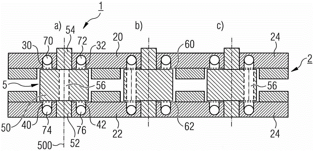
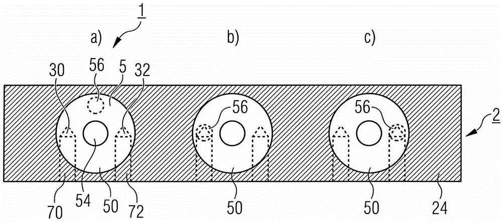
[0034] exist figure 1 A schematic cutaway side view of the proposed valve 1 is shown in , while in figure 2 Its corresponding schematic cross-sectional top view is shown in . exist figure 1 and figure 2 , three identical valves 1 arranged side by side are shown here respectively, labeled a), b) and c), wherein the three valves 1 are in figure 1 and figure 2 are in different on-off states. However, the following will mainly refer to the following examples figure 1 a) in and figure 2 Valve 1 shown in a).

[0035] Equipped with valve body 2, it is in such as figure 1 and figure 2 The illustrated embodiment has an upper port...


PUM


Abstract

The valve (1) has a filling element of a beverage bottling plant. A valve portion (2) has an input channel (30) associated with an output channel (40). An actuating element (5) with passage channel (56) configured for selectively establishing a fluid connection between the input channel and said output channel. The passage channel is provided parallel to a rotation shaft (500) by extending the actuating element. An independent claim is included for a filling organ of beverage bottling plant.

Description

technical field [0001] The invention relates to a valve for a beverage filling machine, preferably a valve for a filling mechanism of a beverage filling machine, for example for switching a material flow or a gas flow and / or for flushing Other fluid streams for sweeping, venting, vacuuming, prefilling, unloading, and / or cleaning containers or filling mechanisms. Background technique [0002] In common beverage filling machines, valves are used in different areas to control fluid flow. In particular, a valve is arranged, for example as a material valve, in the region of the filling mechanism of the beverage filling machine for switching the material flow to the container to be filled. Also, valves are usually provided on the filling mechanism for controlling the gas. For example, when filling a container with carbonated beverages, it is usually filled with a filling gas such as CO before filling. 2 To prefill the container, in order to avoid excessive foaming of the carbon...

Claims


Application Information

Patent Timeline
Patent Type & Authority Patents(China)
IPC IPC(8): B67C3/12
CPCB67C3/28F16K3/085F16K11/074F16K11/20F16K27/003
Inventor 弗洛里安·安格雷尔
Owner KRONES AG
Why Eureka
Try Eureka