Emc-filter for suppressing noise signals

An electromagnetic compatibility and interference suppression technology, applied in the direction of fixed signal inductance, inductor, crosstalk/noise/electromagnetic interference reduction (and other directions, can solve the problems of time-consuming, high cost, etc.

Active Publication Date: 2019-03-19
HANON SYST
View PDF6 Cites 1 Cited by
  • Summary
  • Abstract
  • Description
  • Claims
  • Application Information

AI Technical Summary

Problems solved by technology

[0020] A disadvantage of such passive EMC filters is that they require a large installation space, for example on the main circuit board, for filtering large interference amplitudes or for observing correspondingly low limit values.
It is therefore very frequently necessary to: Time-consuming and cost-intensive adaptation of the layout of the converter circuit board to the proposed specifications
[0022] Due to the described disadvantages, there is a need for a suitable solution which limits the variety of required deformations of the inverter circuit board

Method used


Image

  • Emc-filter for suppressing noise signals
  • Emc-filter for suppressing noise signals
  • Emc-filter for suppressing noise signals

Examples


Embodiment Construction

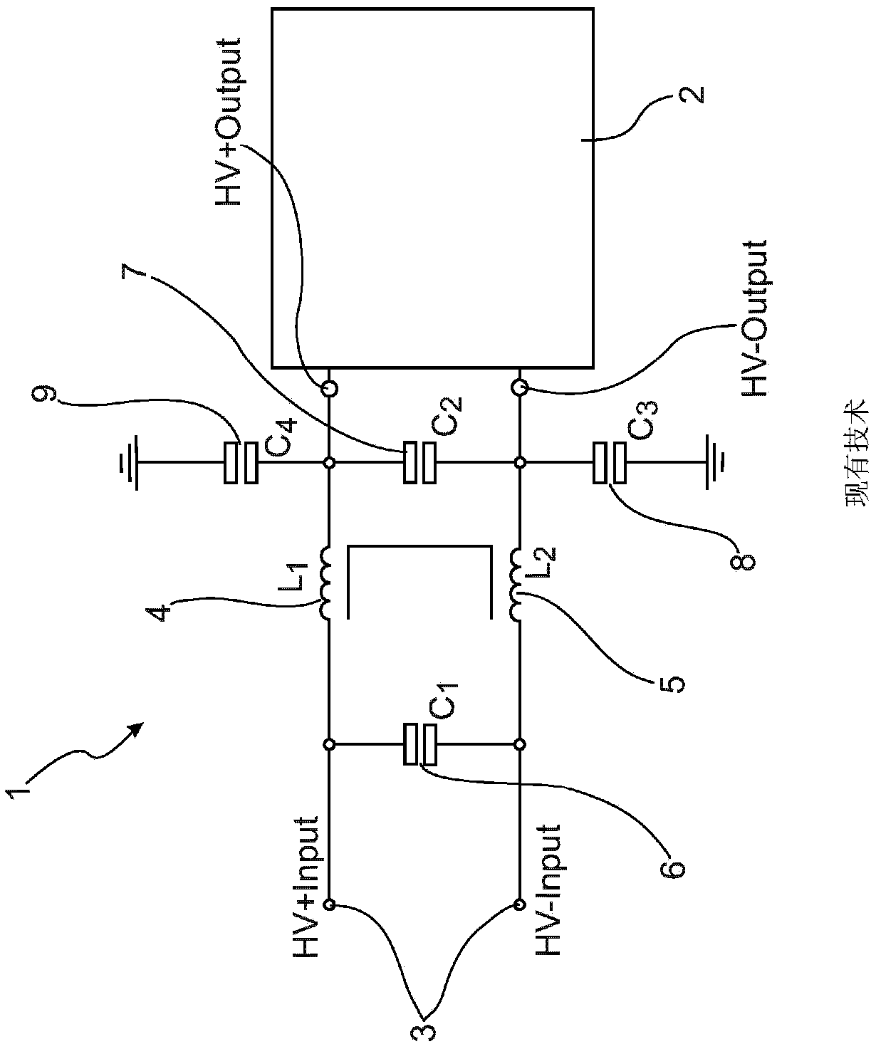
[0046] figure 1 An exemplary circuit arrangement of a passive EMC filter 1 according to the prior art is shown, which is connected to a converter 2 . The EMV filter circuit 1 configured as a passive filter has an input 3 to which a voltage of, for example, 400 V can be applied and includes choke coils L arranged in the supply lines HV+ and HV− 1 4 and L 2 5. The chokes in the case of common mode chokes are arranged on a common core with winding turns L 1 4 and L 2 5 composition.

[0047] with reference sign C 1 A first capacitor 6 is arranged between the conductors HV+ and HV- directly at the input of the passive EMV filter circuit 1 and at the choke L 1 4 and L 2 5, while having the reference designation C 2 The second capacitor 7 in the choke L 1 4 and L 2 5 is then arranged at the output of the EMV filter circuit 1 and thus at the input of the converter 2 .

[0048] with reference sign C 3 The third capacitor 8 is arranged between the conductor HV− and gr...


PUM


Abstract

The invention which relates to an EMC filter for the suppression of interference signals addresses the problem of specifying a solution with which reworking expenditures of an inverter board are reduced and, additionally, installation space restriction as well as reduction of development and production costs are attained. This problem is resolved thereby that in an EMC filter module (10) at leastone core (11) of a choke (4, 5) with a winding (16) is disposed on a first mounting board (14), that at least one of the capacitors (6, 7, 8, 9) is disposed on the first mounting board (14), that thefirst mounting board (14) comprises at least two contact means (17) and that the first mounting board (14) of the EMC filter module (10) is disposed with its contact means (17) on a main board (12) ofan inverter (2) and is electrically connected thereto.

Description

technical field [0001] The invention relates to an EMV filter for suppressing interference signals, the EMV filter having at least one choke coil, at least one core and a plurality of capacitors. Background technique [0002] In electronic components that carry out switching processes with the aid of voltage or current, these switching processes lead to the generation of disturbances, which are caused by the electrical pulses that occur, with the transmission of interference signals. These disturbances can propagate not only via wired connections but also via free space, ie wirelessly, as electromagnetic waves. [0003] The ability of a technical device not to interfere with or be disturbed by other devices by undesired electrical or electromagnetic interactions is known as Electromagnetic Compatibility (EMV). [0004] In order to avoid or minimize the propagation of such interference, it is known from the prior art that these components be equipped with filter units, so-ca...

Claims


Application Information

Patent Timeline
Patent Type & Authority Applications(China)
IPC IPC(8): H02M1/44H02M1/14
CPCH02M1/14H02M1/44H01F17/062H01F27/40H01F2017/065H01F2027/065H02M7/003H03H2001/0035H05K1/0233H05K1/141H05K3/366H05K2201/042H05K2201/1006H03H1/0007H03H7/0138H03H11/32H01F27/24H01F27/28H03H1/00H03H7/0115H03H7/427H05K1/09H05K1/111H05K1/144H05K2201/10015H05K2201/1003H05K2201/10386H05K2201/10409
Inventor 斯特凡·韦尔克霍尔格·格贝里希托马斯·比特尼古劳斯·博施曼
Owner HANON SYST
Why Eureka
Try Eureka