Beamed yarn half dip-dyeing suction space dye device and method

A technology of warp beam yarn and warp beam, which is applied in the field of space dyeing, can solve the problems of monotony, no novelty, no novel style, single full-color style, etc., and achieve the effect of satisfying design and aesthetics, rich layers, and colorful fabric colors

Active Publication Date: 2014-01-15
常州东方伊思达染织有限公司
View PDF6 Cites 1 Cited by
  • Summary
  • Abstract
  • Description
  • Claims
  • Application Information

AI Technical Summary

Problems solved by technology

[0002] The existing warp yarn dyeing method can only form a single full-color style on the warp yarn, but cannot form a regular section dyeing style, resulting in the pattern and color style of the cloth surface can only be determined by warp yarns of different colors. Shaft yarns are combined and woven, and the

Method used


Image

  • Beamed yarn half dip-dyeing suction space dye device and method
  • Beamed yarn half dip-dyeing suction space dye device and method
  • Beamed yarn half dip-dyeing suction space dye device and method

Examples


Example Embodiment

[0033] Example 1

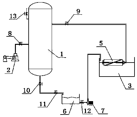
[0034] Such as figure 1 As shown, the present invention discloses a semi-dipping and suction section dyeing device for warp yarn. The device is composed of a vacuum system, a suction system, and a circulation system. The vacuum system includes a vacuum tank (1) and a matching Vacuum pump (2) for evacuating. The suction system includes a dye tank (3) and a dye column (4) fixed in the tank and used to sleeve the warp beam (5). The circulation system includes a liquid storage tank (6) and a The suction pump (7) at the lower or lower end of the liquid storage tank (6); wherein the middle and upper part of the vacuum tank (1) is connected to one end of the dye column (4) through a No. 1 pipe, and the The lower part of the vacuum tank (1) is connected to the liquid storage tank (6) through the second pipeline, and the liquid storage tank (6) is connected to the liquid storage tank (6) through the suction pump (7) and the third pipeline Connect the dye cell (3).

[0...

Example Embodiment

[0055] Example 2

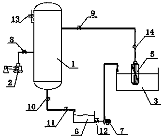
[0056] Such as figure 2 As shown, the present invention discloses a semi-dipping and suction section dyeing device for warp yarn. The device is composed of a vacuum system, a suction system, and a circulation system. The vacuum system includes a vacuum tank (1) and a matching Vacuum pump (2) for evacuating. The suction system includes a dye tank (3) and a dye column (4) fixed in the tank and used to sleeve the warp beam (5). The circulation system includes a liquid storage tank (6) and a The suction pump (7) at the lower or lower end of the liquid storage tank (6); wherein the middle and upper part of the vacuum tank (1) is connected to one end of the dye column (4) through a No. 1 pipe, and the The lower part of the vacuum tank (1) is connected to the liquid storage tank (6) through the second pipe, and the liquid storage tank (6) is connected to the liquid storage tank (6) through the suction pump (7) and the third pipe Connect the dye cell (3).

[0057] T...


PUM

PropertyMeasurementUnit
Densityaaaaaaaaaa

Abstract

The invention provides a beamed yarn half dip-dyeing suction space dye device and method. The beamed yarn half dip-dyeing suction space dye device is composed of a vacuumizing system, a suction system and a circulating system. The vacuumizing system comprises a vacuum tank and a vacuum pump used for vacuumizing the vacuum tank. The suction system comprises a dye tank, a dye pillar is arranged inside the dye tank, and one or more wrap beams are connected to the dye pillar in a sleeved mode. The circulating system comprises a liquid storage tank and a material sucking pump is arranged at one end of the liquid storage tank. A first pipeline on the vacuum tank is connected with the dye pillar, a second pipeline at the bottom end of the vacuum tank is connected with the liquid storage tank, and a third pipeline at one side of the liquid storage tank is connected with the dye tank through the material sucking pump. The beamed yarn half dip-dyeing suction space dye method by utilizing the device comprises the steps of barrel looseness, cage loading, mixing of dye liquid, suction and space dye, cage unloading, warp beam wrapping, cool stacking and postprocessing.

Description

technical field [0001] The invention relates to the field of section dyeing, in particular to a suction section dyeing device and method for warp beam yarn semi-dip dyeing. Background technique [0002] The existing warp yarn dyeing method can only form a single full-color style on the warp yarn, but cannot form a regular section dyeing style, resulting in the pattern and color style of the cloth surface can only be determined by warp yarns of different colors. Shaft yarns are combined and woven, and the fabric woven by the colored yarns is neat and regular according to the designed flower shape. Since each yarn has only one color from the beginning to the end, the style of the woven fabric is monotonous and dull, with different colors. Rich, without the novelty that space dyed yarn combinations can produce. Contents of the invention [0003] In order to solve the deficiencies in the prior art, the present invention develops a suction section dyeing device for warp beam ...

Claims


Application Information

Patent Timeline
IPC IPC(8): D06B1/00D06B23/04
Inventor 恽中方
Owner 常州东方伊思达染织有限公司
Why Eureka
Try Eureka