positive displacement pump

A technology of positive displacement pump and pump assembly, applied in the direction of pump, rotary piston pump, pump element, etc., can solve the problem of cover and control board wear, etc., and achieve the effect of preventing slight movement and avoiding end-side wear

Active Publication Date: 2017-03-08
PUMP TECH SOLUTIONS PS GMBH
View PDF10 Cites 0 Cited by
  • Summary
  • Abstract
  • Description
  • Claims
  • Application Information

AI Technical Summary

Problems solved by technology

Another disadvantage here is that micro-movements that occur in this way lead to wear on the cover and the control board

Method used


Image

  • positive displacement pump
  • positive displacement pump
  • positive displacement pump

Examples


Embodiment Construction

[0020] The invention will be described below on the basis of a two-stroke vane pump. However, the invention can of course also be used for roller vane pumps.

[0021] Sliding vane pumps are well known. For this purpose, reference is made, for example, to the aforementioned patent documents, so only the components relevant to the invention will be described in detail below.

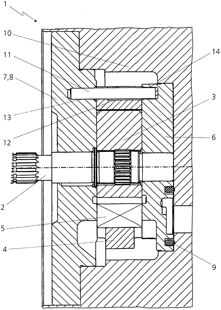
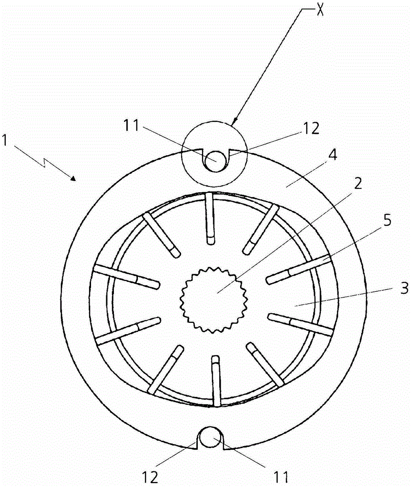
[0022] The sliding vane pump 1 has a rotor 3 arranged on a drive shaft 2 , a cam ring 4 surrounding the rotor 3 and a plurality of working slides 5 in the form of vanes arranged in slots on the periphery of the rotor 3 . Control plates 6 and 7 are provided on both sides of the rotor 3 and the cam ring 4 . In the exemplary embodiment shown, the control board 7 is integrated in the cover 8 or forms the cover. In the control plates 6 and 7 supply and rear slide supply bends (not shown) are formed in known manner. The seal 9 is used to ensure a seal against the pressure medium, usually oil, to the outside....


PUM


Abstract

The pump e.g. two-stroke vane pump (1), has work chambers formed between a curve ring (4) and a rotor (3). Position pins (11) are arranged in an axial direction and pushed through axial grooves (12) of the curve ring and inserted into holes (13, 14) of light metal control plates (6, 7). The rotor is driven by a drive shaft (2). The axial grooves comprise a groove bottom with a rounded part. Extending side walls are closed at the groove bottom. Spacing of the side walls from each other is enlarged over diameters of the position pins in an increasing manner. The curve ring is made of iron.

Description

technical field [0001] The invention relates to a positive displacement pump for conveying a pressure medium to a load, in particular a two-stroke sliding vane or roller vane pump for a transmission of a motor vehicle. Background technique [0002] Vane or rotary vane pumps are known, for example, from DE 199 09 963 B4, DE 10 2006 052 996 A1 and DE 102 29 809 A1. [0003] Positive displacement pumps have a pump assembly with a rotor, a cam ring and working slides, such as slide plates or rollers, in which a single working chamber is formed. The rotor is delimited by the control plate on both end faces or in the axial direction. The control board can also be integrated on one side into the cover of the displacement pump or formed by the cover. [0004] When the positive displacement pump is pushed into the bowl-shaped recess into a housing, for example of a vehicle transmission, the cam ring is usually positioned with two positioning pins relative to the control panel cover...

Claims


Application Information

Patent Timeline
Patent Type & Authority Patents(China)
IPC IPC(8): F04C2/344F04C15/00
CPCF01C21/106F04C2/3446F04C14/223
Inventor J·默茨
Owner PUMP TECH SOLUTIONS PS GMBH
Why Eureka
Try Eureka