Rotary compressor and crank shaft piston assembly thereof

A rotary compressor and piston assembly technology, applied in the field of compressors, can solve the problems of shortening the service life of the compressor, shortening the life of the compressor, increasing the wear of the thrust surface, etc., to reduce the working noise, improve the compression capacity, and improve the wear the effect of the situation

Inactive Publication Date: 2014-01-15
ANHUI MEIZHI PRECISION MFG
View PDF8 Cites 19 Cited by
  • Summary
  • Abstract
  • Description
  • Claims
  • Application Information

AI Technical Summary

Problems solved by technology

Due to the eccentric structure, the vibration and noise of this type of compressor are relatively large, which shortens the service life of the compressor. Moreover, the thrust surface of the traditional compressor has a non-centrosymmetric structure, and the oil film is unevenly distributed on the thrust surface, which increases the Thrust surface wear, further shortening compressor life

Method used


Image

  • Rotary compressor and crank shaft piston assembly thereof
  • Rotary compressor and crank shaft piston assembly thereof
  • Rotary compressor and crank shaft piston assembly thereof

Examples


Embodiment Construction

[0038]Embodiments of the present invention are described in detail below, examples of which are shown in the drawings, wherein the same or similar reference numerals designate the same or similar elements or elements having the same or similar functions throughout. The embodiments described below by referring to the figures are exemplary and are intended to explain the present invention and should not be construed as limiting the present invention.

[0039] In describing the present invention, it should be understood that the terms "center", "longitudinal", "transverse", "length", "width", "thickness", "upper", "lower", "front", " Orientation or position indicated by "back", "left", "right", "vertical", "horizontal", "top", "bottom", "inner", "outer", "clockwise", "counterclockwise", etc. The relationship is based on the orientation or positional relationship shown in the drawings, and is only for the convenience of describing the present invention and simplifying the descript...


PUM


Abstract

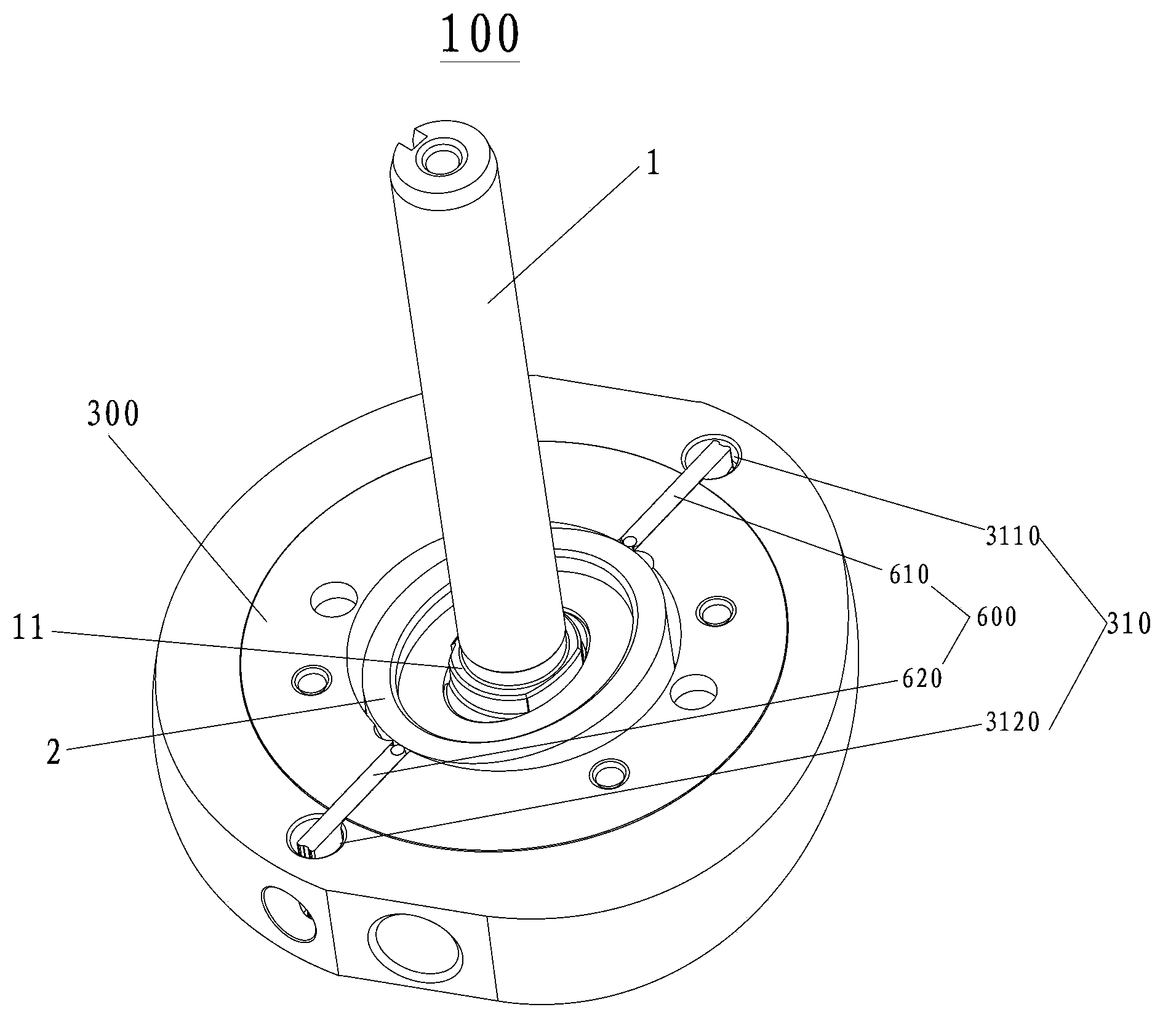
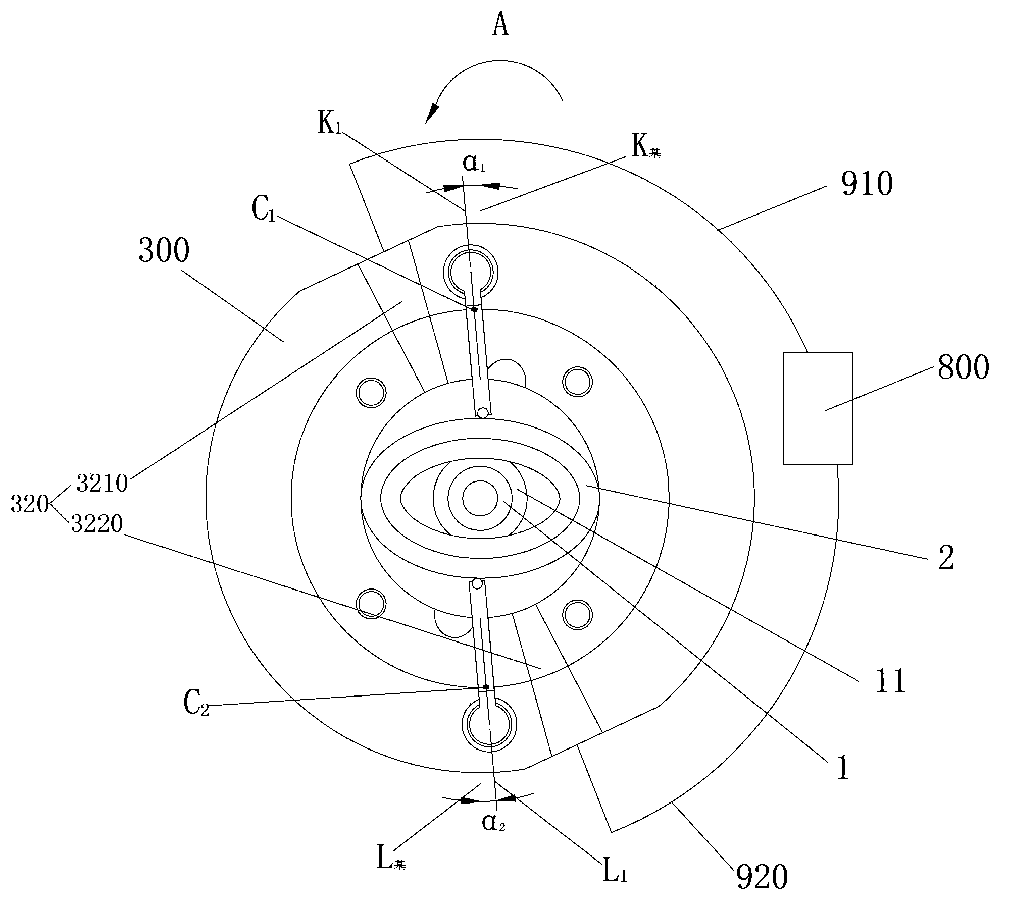
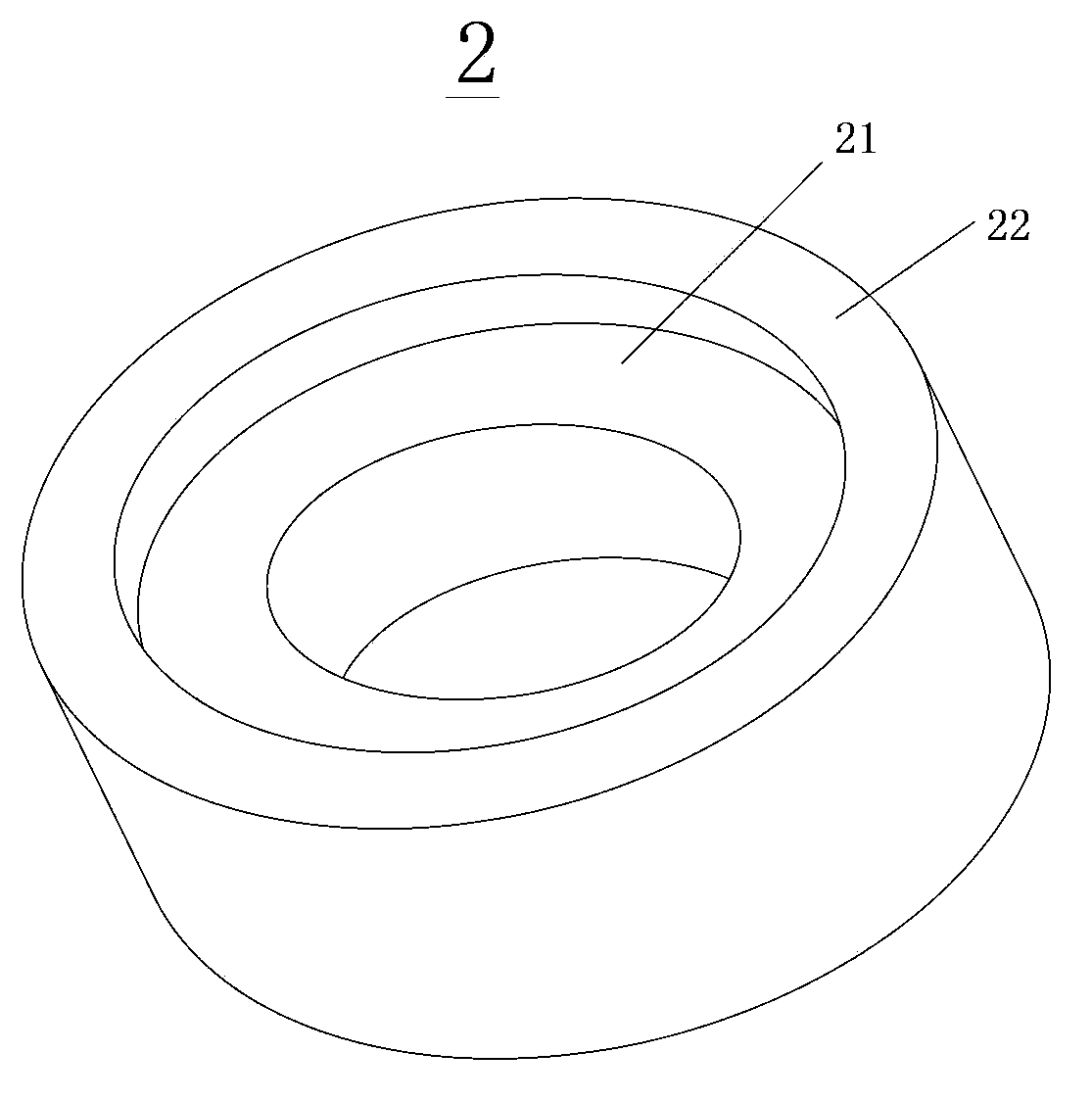
The invention discloses a rotary compressor and a crank shaft piston assembly thereof. The crank shaft piston assembly comprises a crank shaft and a piston, wherein the crank shaft is provided with a driving part, the lower end surface of the driving part is a thrust surface to be supported on a subsidiary bearing of the rotary compressor, and a cross section of the driving part, which is orthogonal to the axial direction of the crank shaft, is of a centrosymmetric pattern relative to the central axis of the crank shaft; the piston is sleeved on the driving part, the cross section of the periphery surface of the piston, which is orthogonal to the axial direction of the crank shaft, is an ellipse, and the central axis of the piston is coincided with the central axis of the crank shaft. The crank shaft piston assembly provided by the invention does not have an exocentric structure, the operation is smooth and stable when the rotary compressor operates, the thrust surface is of a centrosymmetric structure, and therefore a dynamic oil film is uniformly formed on the thrust surface, the load of the thrust surface is uniformly distributed, and the performance of the rotary compressor is favorably improved. The invention also discloses the rotary compressor.

Description

technical field [0001] The invention relates to the technical field of compressors, in particular to a crankshaft-piston assembly for a rotary compressor and a rotary compressor with the same. Background technique [0002] The traditional rotary compressor includes a compression assembly and a motor assembly arranged in the housing. The compression assembly includes a cylinder, a piston arranged in the cylinder, a crankshaft that drives the piston to rotate eccentrically, and a sliding vane arranged in the sliding vane groove of the cylinder. The main bearing and the auxiliary bearing are arranged on both sides of the cylinder, and one end of the sliding plate is in contact with the outer circumference of the piston. The motor assembly includes a stator and a rotor. The stator is fixed on the inner wall of the housing, and the rotor is fixed on the crankshaft. Due to the eccentric structure, this type of compressor has relatively large vibration and noise, which shortens the...

Claims


Application Information

Patent Timeline
Patent Type & Authority Applications(China)
IPC IPC(8): F04C18/356F04C29/00F04C29/12
Inventor 李振旺吴延平
Owner ANHUI MEIZHI PRECISION MFG
Why Eureka
Try Eureka