Supporting device of annular superconducting magnet

A technology of superconducting magnets and supporting devices, which is applied in the directions of supporting machines, machines/brackets, AC network load balancing, etc., to achieve the effects of strong reliability, high stability and not easy to side slip

Inactive Publication Date: 2014-01-15
HUAZHONG UNIV OF SCI & TECH
View PDF6 Cites 8 Cited by
  • Summary
  • Abstract
  • Description
  • Claims
  • Application Information

AI Technical Summary

Problems solved by technology

[0006] The invention provides a ring-type superconducting magnet support device, which solves the problem that the huge electromagnetic force received by the ring-type high-temperature superconducting magnet in the existing superconducting magnetic energy storage device has a negative impact on the magnet system, so as to improve the mechanical Stability and running stability

Method used


Image

  • Supporting device of annular superconducting magnet
  • Supporting device of annular superconducting magnet
  • Supporting device of annular superconducting magnet

Examples


Embodiment Construction

[0034] The present invention will be further described below with reference to the drawings and embodiments. It should be understood that the specific embodiments described here are only used to explain the present invention, and are not intended to limit the present invention.

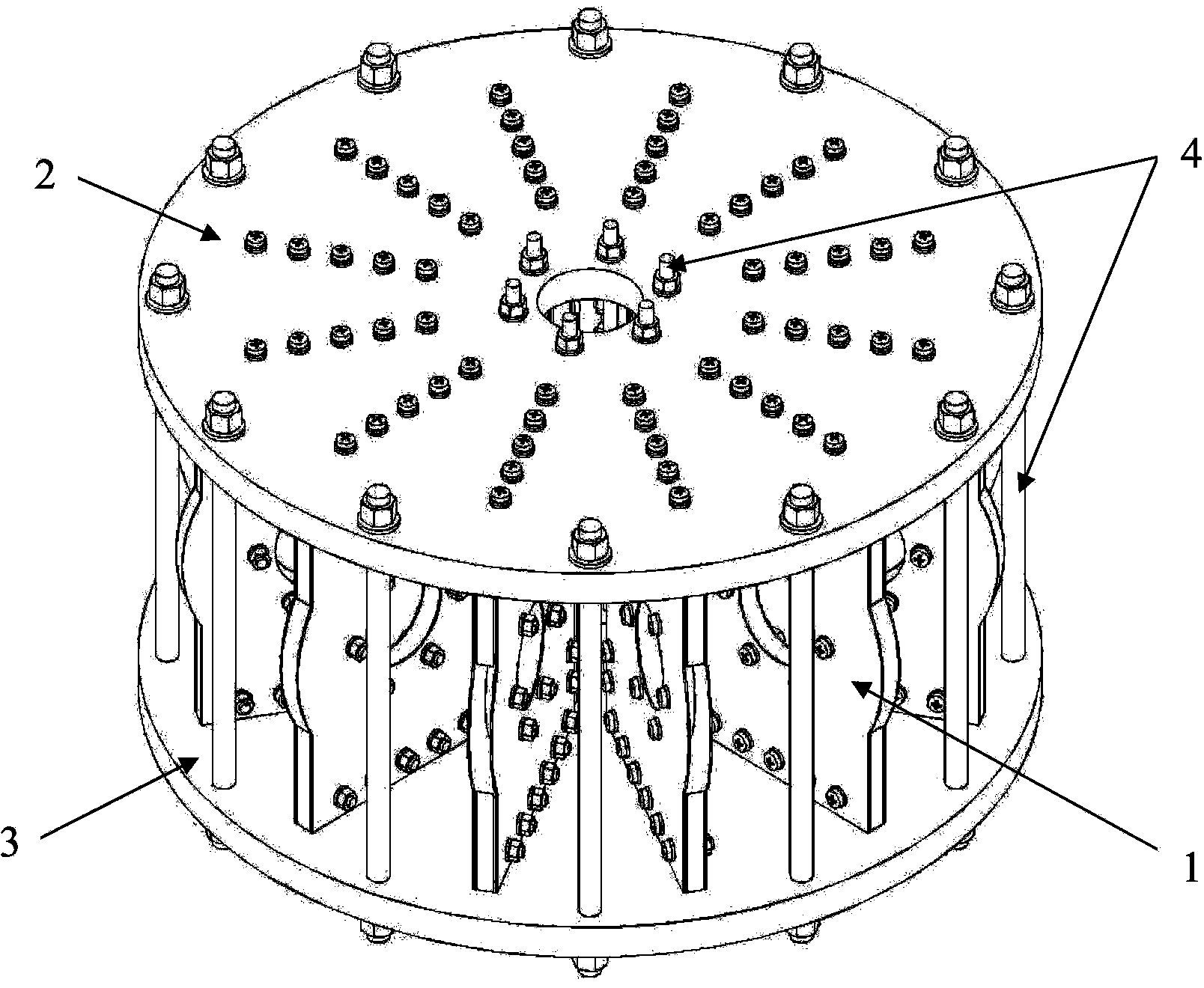
[0035] Such as figure 2 As shown, the embodiment of the present invention includes 12 superconducting magnet clamping assemblies 1 and upper end cover 2 and lower end cover 3; 12 superconducting magnet clamping assemblies are between the upper and lower end covers, radially and vertically uniformly along the circumference Place it vertically, and the upper and lower end covers are connected and fixed by the long screw 4.

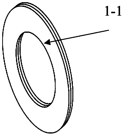
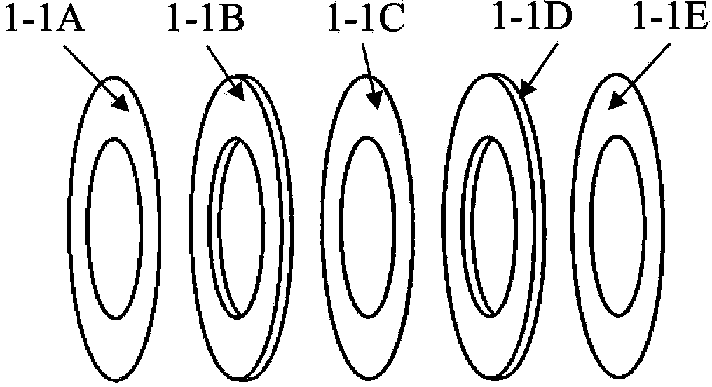
[0036] Such as Figure 3(a) ~ Figure 3(f) As shown, the superconducting magnet clamping assembly 1 is composed of an inner support ring 1-2, an outer fixing plate 1-3, a left cover plate 1-4 and a right cover plate 1-5, and the inner support ring 1-2 It is circular and embedded in...


PUM


Abstract

The invention provides a supporting device of an annular superconducting magnet and belongs to superconducting double-cake supporting devices of superconducting magnetic energy storing devices. The supporting device of the annular superconducting magnet solves the problem that huge electromagnetic force exerted on superconducting magnets has the negative effect on a magnet system in an existing superconducting magnetic energy storing device. The annular device of the annular superconducting magnet comprises N superconducting magnet clamping assemblies. Each superconducting magnet clamping assembly is composed of an inner supporting ring, an outer fixing plate, a left cover plate and a right cover plate. The superconducting magnet clamping assemblies are evenly and vertically placed between an upper end cover and a lower end cover along the circumference in a radial mode. The upper end cover and the lower end cover are connected and fixed with each other through long screws. In the work state, each superconducting double-cake inner ring side is supported by an inner supporting ring, and the two sides of each superconducting double-cake are fastened through one left cover plate and one right cover plate. The upper end and the lower end of each superconducting double-cake are fixed through one outer fixing plate, and therefore a modular magnet work assembly is formed. A plurality of magnet work assemblies are evenly and vertically placed between the upper end cover and the lower end cover along the circumference in the radial mode, annular supporting and fixing are conducted, and the mechanical stability and the operational stability of the annular superconducting magnet are improved.

Description

technical field [0001] The invention belongs to a superconducting double cake supporting device of a superconducting magnetic energy storage device, in particular to a ring-shaped superconducting magnet supporting device. Background technique [0002] Superconducting magnetic energy storage devices have become an important energy storage solution in modern power systems because of their characteristics of adjusting peak loads of power systems, compensating low-frequency power of power systems, suppressing voltage dips, and improving the stability of power systems. [0003] The core of the superconducting magnetic energy storage device is a superconducting magnet, which is usually composed of multiple superconducting double cakes electrically connected, as shown in Figure 1, the superconducting double cakes 1-1 are circular, from left to right The sequence consists of left epoxy ring 1-1A, left coil 1-1B, middle epoxy ring 1-1C, right coil 1-1D and right epoxy ring 1-1E, left...

Claims


Application Information

Patent Timeline
Patent Type & Authority Applications(China)
IPC IPC(8): F16M11/22H02J3/28
Inventor 唐跃进刘豪邓序之任丽
Owner HUAZHONG UNIV OF SCI & TECH
Why Eureka
Try Eureka