
Touch device

A touch device and touch area technology, which can be applied to instruments, electrical digital data processing, and input/output processes of data processing, etc., can solve problems such as frame width, and achieve the effect of narrow frame

Inactive Publication Date: 2014-01-15
INTERFACE OPTOELECTRONICS SHENZHEN +1
View PDF6 Cites 14 Cited by
  • Summary
  • Abstract
  • Description
  • Claims
  • Application Information

AI Technical Summary

Problems solved by technology

Since the sensing series of the existing touch electrodes are directly connected to the connection traces in the same plane, the reserved area exists, thus making the frame of the existing touch device wider

Method used


Image

  • Touch device
  • Touch device
  • Touch device

Examples


Embodiment Construction

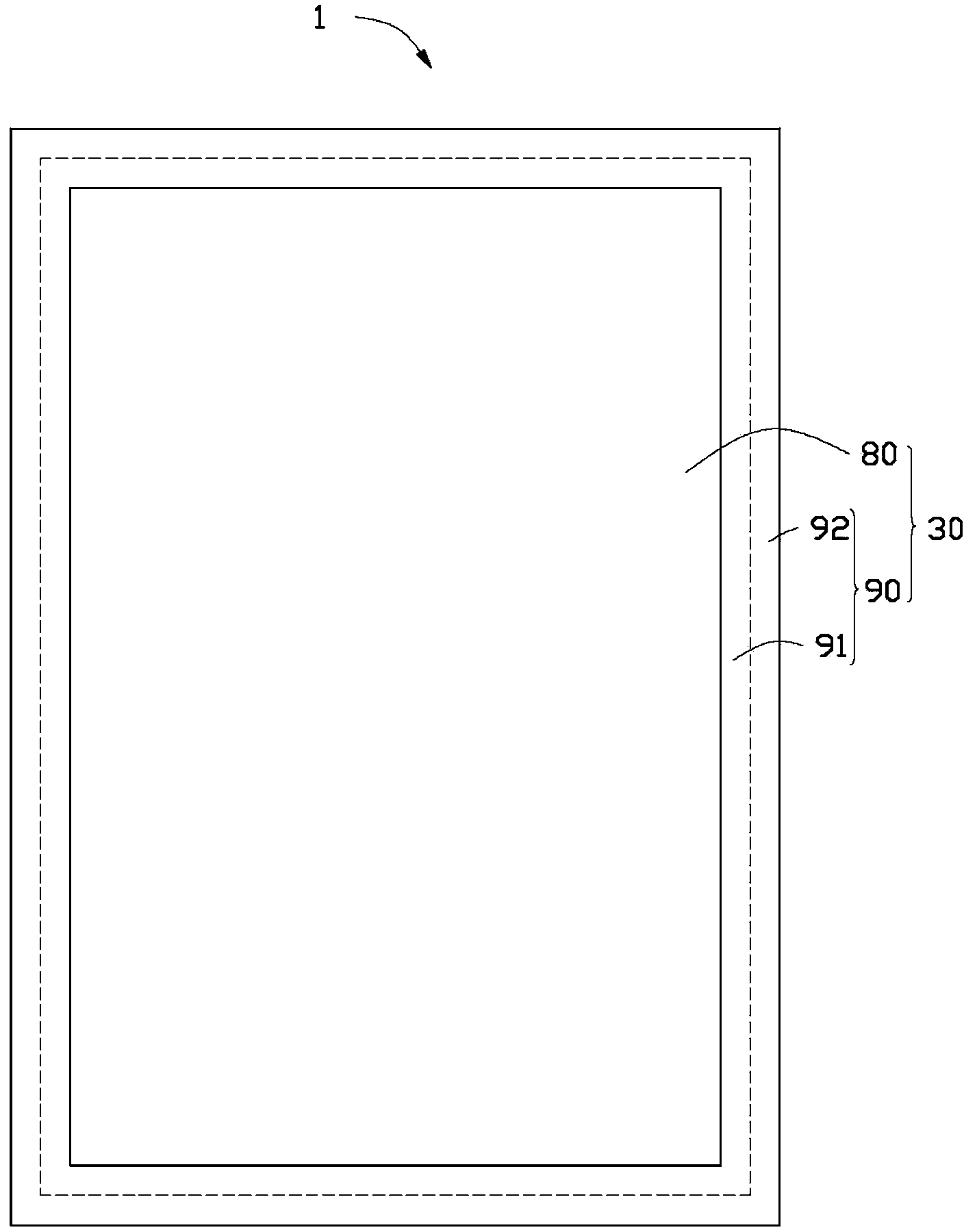
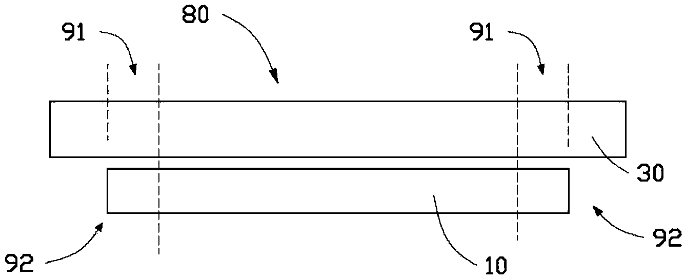
[0030] see figure 1 , figure 1 It is a schematic diagram of the touch panel structure 30 of the touch device 1 according to the specific embodiment of the present invention. The touch device 1 has a touch panel 30 , and the touch panel 30 includes a display area 80 located in the middle of the touch panel 30 and a frame area 90 located around the display area 80 . Wherein, the display area 80 is a light-transmitting area for displaying images. The frame area 90 is a non-transparent area located on the periphery of the display area 80 . In this embodiment, the frame area 90 includes a touch area 91 and a wiring area 92 . The touch area 91 is located between the display area 80 and the wiring area 92 , and both the display area 80 and the touch area 91 are operable areas of the touch function of the touch device 1 .

[0031] see figure 2 , figure 2 It is a schematic diagram of the side structure of the touch device 1 . The touch device 1 includes a display panel 10 and ...


PUM


Abstract

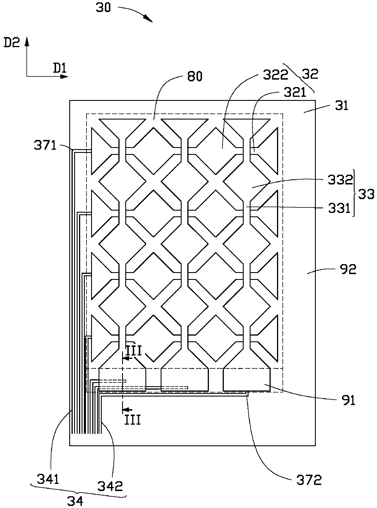
A touch device comprises a light-transmitting display region and a non-light-transmitting frame region located on the outer side of the display region, wherein the frame region comprises a touch region and a wiring region. The touch region is arranged between the display region and the wiring region, multiple sensing pads for sensing touch operations are distributed in the display region and the touch region according to a specific rule, and multiple connecting path lines are located in the wiring region and electrically connected with the corresponding sensing pads and are used for being connected with the sensing pads and a drive circuit so as to obtain electrical signals. The ends of at least a part of the connecting path lines electrically connected with the sensing pads extend into the touch region, the part of the connecting path lines and the sensing pads are stacked in arrangement, insulating layers are arranged between the sensing pads and the connecting path lines which are stacked, a plurality of through holes are formed in the insulating layers, and the sensing pads located in the touch region are electrically connected with the corresponding connecting path lines in the wiring region. The touch device is narrow in frame.

Description

technical field [0001] The invention relates to a touch device. Background technique [0002] Currently, touch devices with touch functions are more and more commonly used. Generally speaking, a touch device includes a display panel and a touch panel. Wherein, the touch panel can be built into the display panel or attached to the display panel. At present, touch panels are roughly classified into resistive touch panels, optical touch panels, and capacitive touch panels according to different sensing methods. [0003] The interface circuit of the resistive touch panel is mainly a serial port data circuit and a USB data interface circuit, generally there are four-wire and five-wire systems. The panel part of the resistive touch panel is a multi-layer composite film. Taking the four-wire resistive touch panel as an example, the four-wire resistive touch panel is covered with two layers between the surface protective coating and the substrate. Transparent conductive layer, t...

Claims


Application Information

Patent Timeline
IPC IPC(8): G06F3/041
Inventor 曾启源陈彦华
Owner INTERFACE OPTOELECTRONICS SHENZHEN
Learn More