Shell type transformer lead clamping structure and clamping method

A shell-type transformer and lead wire clamping technology, applied in the field of transformers, can solve the problems of inconvenient operation, complex structure, poor lead wire clamping firmness and reliability, etc. Effect

Active Publication Date: 2014-01-15
BAODING BAOLING TRANSFORMER
View PDF4 Cites 5 Cited by
  • Summary
  • Abstract
  • Description
  • Claims
  • Application Information

AI Technical Summary

Problems solved by technology

A shell-type transformer is a type of transformer in which the iron core and yoke composed of laminations surround the winding (generally surrounding most of the winding). The wire cake of the shell-type transformer is placed vertically, and the lead wires are drawn from the upper part of the wire cake. Background The technical problems are: complex structure, inconvenient operation, poor firmness and reliability of lead clamping

Method used


Image

  • Shell type transformer lead clamping structure and clamping method
  • Shell type transformer lead clamping structure and clamping method
  • Shell type transformer lead clamping structure and clamping method

Examples


Embodiment Construction

[0015] The present invention will be further described through the embodiments below in conjunction with the accompanying drawings.

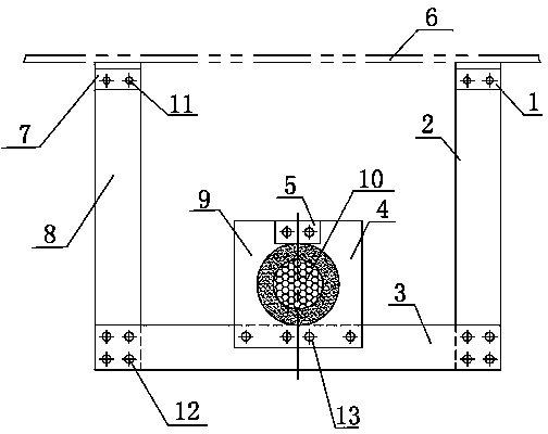
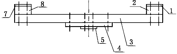
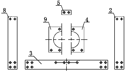
[0016] A shell-type transformer lead wire clamping structure, including lead wire 10, box cover 6, fixed plate 1, fixed plate 2 7, support plate 2, support plate 2 8, horizontal plate 3, lead splint 1 4, lead splint 2 9 and the lead wire fixing plate 5, the fixing plate one and the fixing plate two are welded on the case cover, the support plate one and the support plate two are vertically arranged with the case cover, one end of the support plate one and the support plate two is respectively connected with the fixing plate one and the fixing plate Two fixed connections, the other ends of support plate 1 and support plate 2 are respectively fixedly connected with the two ends of the horizontal plate, and the horizontal plate is arranged parallel to the box cover; the lead splint 1 and the lead splint 2 are respectively provided with semicircular ...


PUM


Abstract

The invention relates to a shell type transformer lead clamping structure and clamping method, and belongs to the technical field of transformers. According to the technical scheme, a first fixing plate and a second fixing plate are welded to a box cover, one end of each first supporting plate and one end of each second supporting plate are fixedly connected with the first fixing plate and the second fixing plate respectively, the other end of each first supporting plate and the other end of each second supporting plate are fixedly connected with the two ends of transverse plates respectively, a lead passes through a circular hole formed by matching two semicircular holes which are formed in a first lead clamping plate and a second lead clamping plate, the first lead clamping plate and the second lead clamping plate are fixed to the middle of the transverse plates respectively, the other end of the first lead clamping plate and the other end of the second lead clamping plate are fixed together through a lead fixing plate, and the shell type transformer lead is clamped and fixed. According to the clamping structure and clamping method, the supporting plates and the transverse plates are connected vertically and horizontally, the lead is firmly fixed by the semicircular holes of the lead clamping plates, on the premise that shell type transformer lead meets the insulation distance, the clamping structure is simple in structure, reliable in fixation and convenient to operate, the lead is lengthened to electric creep distance of the box cover to the maximum extent, and performance of products is guaranteed.

Description

technical field [0001] The invention relates to a clamping structure and a clamping method for lead wires of a shell-type transformer, belonging to the technical field of transformers. Background technique [0002] At present, the lead wire clamping of conventional core-type transformer products is mostly welded to the bottom plate on the web of the clamp, and then the lead wire is fixed firmly by the wire clamp under the premise of ensuring the insulation distance. A shell-type transformer is a type of transformer in which the iron core and yoke composed of laminations surround the winding (generally surrounding most of the winding). The wire cake of the shell-type transformer is placed vertically, and the lead wires are drawn from the upper part of the wire cake. Background The technical problems are: complex structure, inconvenient operation, poor firmness and reliability of lead wire clamping. Contents of the invention [0003] The object of the present invention is t...

Claims


Application Information

Patent Timeline
Patent Type & Authority Applications(China)
IPC IPC(8): H01F27/29H01F27/30
Inventor 郑泉福泉王健王维征李习芹郭飞
Owner BAODING BAOLING TRANSFORMER
Why Eureka
Try Eureka