
Kinetic energy battery

A battery and kinetic energy technology, applied to synchronous motors with stationary armatures and rotating magnets, etc., can solve the problems of chemical substances polluting the environment, less battery energy storage, and short battery life, so as to achieve large energy storage and no pollution in life Environment, long life effect

Inactive Publication Date: 2014-01-15
吴德民
View PDF0 Cites 1 Cited by
  • Summary
  • Abstract
  • Description
  • Claims
  • Application Information

AI Technical Summary

Problems solved by technology

[0003] 1. Purpose of the invention: The present invention aims to solve the problems of low battery energy storage, short battery life, and environmental pollution caused by chemical substances in the actual battery, and overcome the technical obstacles that predecessors cannot use kinetic energy. The advantages of polluting the environment, etc., can achieve the technology of using kinetic energy to store energy

Method used


Image

  • Kinetic energy battery
  • Kinetic energy battery
  • Kinetic energy battery

Examples


Embodiment Construction

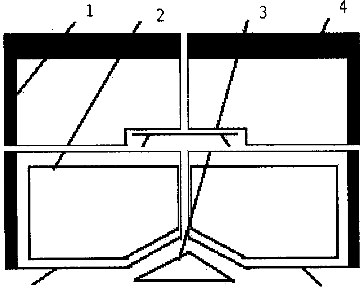
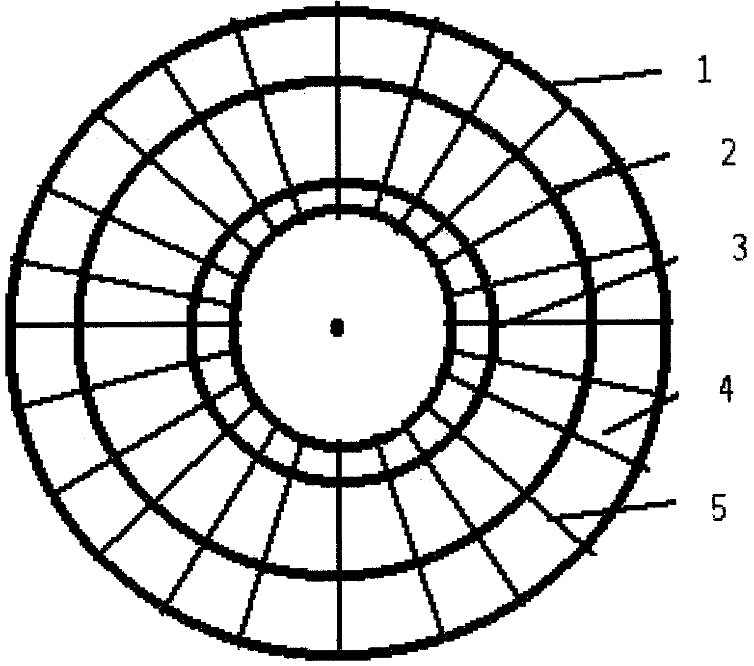
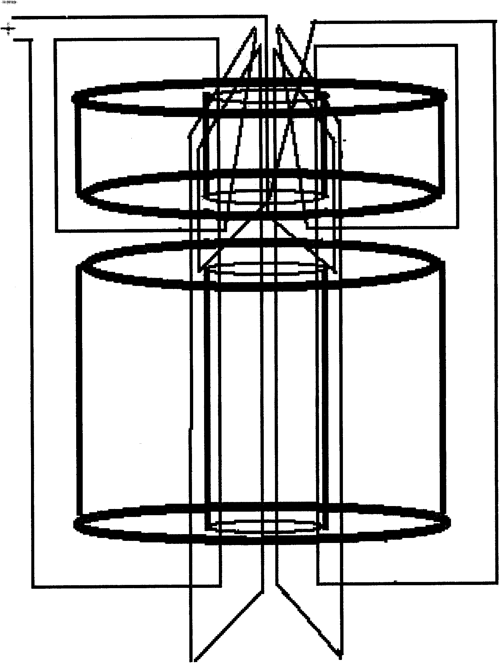
[0010] Concretely divided into, shell ( figure 1 , 1), the rotor ( figure 1 , 2), stator ( figure 1 , 3), magnetic isolation cover ( figure 1 , 4), coil ( figure 2 , 5), iron frame ( Figure 4 ) requires two permanent magnets whose coercive forces are smaller than their respective coercive forces as stators figure 1 , 3 and rotor figure 1 , 2. The diameter of the stator is 8 cm, and it is a cone with a bus bar and the ground at an angle of 30 degrees. The rotor is a permanent magnet with a bottom diameter of 20 cm and a height of 2 cm. There is a depression with a diameter of 8 cm in the middle of the lower surface of the rotor. There is a cavity with a diameter of 2 cm figure 2 , using the principle that the same poles of the magnets repel each other, the cylindrical permanent magnet rotor is lifted up, because the magnetic poles are the same, the middle of the rotor is concave figure 1 , so it will be suspended, and then the outer casing of the rotor is sealed with ...


PUM


Abstract

The invention belongs to a battery in the technical field of rotation dynamics kinetic energy storage and relates to the electro-magnetic induction field. At present, kinetic energy is a kind of performance energy, as the existing kinetic energy on the existing earth can be affected by inhibition friction, nearly no one steps into the kinetic energy storage field, how to store the kinetic energy on the earth becomes the focus of scientific debate, by thinking over the problem, the kinetic energy is not only the energy obtained through high-speed linear motions of objects, the objects also obtain the kinetic energy through rotation of the objects such as earth rotation. According to the battery, the rotation kinetic energy storage technology of the rotation dynamics is fully utilized, based on the magnet mutual repelling principle, a magnet rotor is suspended, then air in cases of an outer mask is totally pumped out for eliminating the friction, then a wire winds around the cases, one object is added to each case, the wire winds around the two cases from the outside of the cases so that wire currents can enter the upper surface and the lower surface of the magnet rotor in the same direction, and therefore electro-magnetic induction is utilized for driving the rotor to rotate. As the interior of the rotor is suspended without the air, the rotor will automatically rotate at a constant speed forever, and electrical energy is converted into the kinetic energy.

Description

Technical field: [0001] The invention belongs to a battery, and the battery relates to the fields of electromagnetic induction and kinetic energy utilization of rotational dynamics. Background technique: [0002] The current batteries are all chemical batteries, which store electrical energy in chemical substances, which is obviously different from the storage of electrical energy into kinetic energy in the present invention. Due to the limited reaction energy of chemical substances in chemical batteries and uncontrolled problems, there is energy storage Less energy, short battery life, and environmental pollution caused by chemical substances in it. Since kinetic energy is a performance energy that is not limited by energy, it has a series of advantages such as large energy storage, long battery life, and no pollution to the environment after being discarded. In terms of electromagnetic technology , although people are very mature to electromagnetic interchange technology, ...

Claims


Application Information

Patent Timeline
IPC IPC(8): H02K21/24
Inventor 吴德民
Owner 吴德民
Learn More