A rotor current recovery feedback device for a slip-wound rotor motor

A rotor motor and feedback device technology, applied in the electronic field, can solve the problems of rotor winding induced current and induced voltage waste, and achieve the effect of saving energy

Inactive Publication Date: 2015-12-16
王成军
View PDF7 Cites 0 Cited by
  • Summary
  • Abstract
  • Description
  • Claims
  • Application Information

AI Technical Summary

Problems solved by technology

[0002] At present, when the slip-wound rotor motor is started, the induced current and induced voltage of the rotor winding are relatively large, resulting in magnetic saturation of the rotor winding. Usually, parallel resistors increase the impedance of the rotor winding to reduce the induced current and induced voltage on the rotor winding. It causes waste of induced current and induced voltage on the rotor winding

Method used


Image

  • A rotor current recovery feedback device for a slip-wound rotor motor
  • A rotor current recovery feedback device for a slip-wound rotor motor

Examples


Embodiment 1

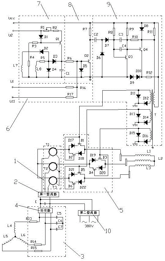
[0031] Embodiment 1 is described by taking a three-phase slip-wound rotor motor as an example.

[0032] Such as figure 1 As shown, a rotor current recovery feedback device for a slip-wound rotor motor includes a frequency conversion and voltage conversion circuit 1 , a first rectifier 2 , an inverter circuit 3 , a chopper circuit 5 and a high frequency oscillation circuit 6 .

[0033] Frequency conversion and voltage conversion circuit 1, changing the frequency and voltage of the rotor winding induced current of the slip-wrapping rotor motor and outputting it;

[0034] The first rectifier 2 is connected to the output end of the frequency conversion and voltage conversion circuit 1, and rectifies the AC voltage output by the frequency conversion and voltage conversion circuit 1;

[0035] The inverter circuit 3 is connected to the output terminal of the first rectifier 2, converts the DC voltage into a three-phase AC voltage, and outputs it to the stator winding of the slip-wra...

Embodiment 2

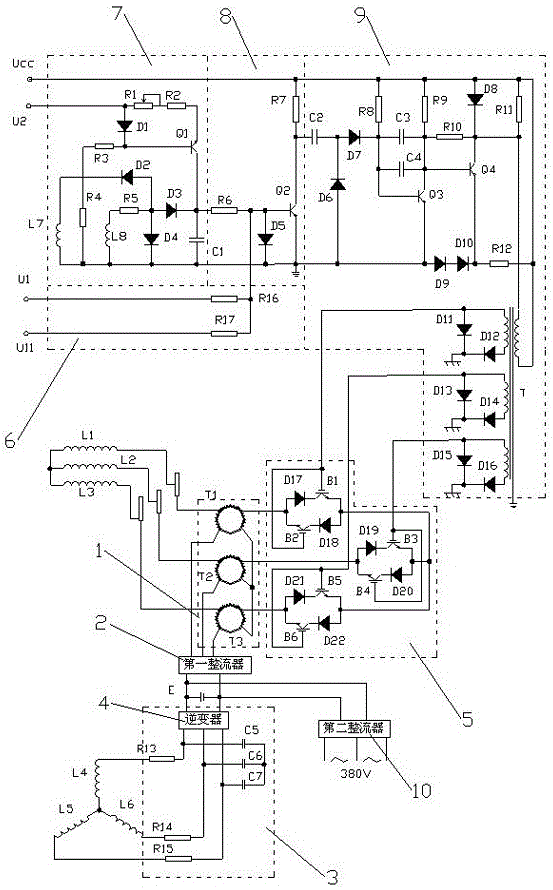
[0050] Embodiment 2 is described by taking a three-phase slip-wound rotor motor as an example.

[0051] Such as figure 2 As shown, a rotor current recovery feedback device for a slip-wound rotor motor includes a frequency conversion and voltage conversion circuit 1 , a first rectifier 2 , an inverter circuit 3 , a chopper circuit 5 and a high frequency oscillation circuit 6 .

[0052] Frequency conversion and voltage conversion circuit 1, changing the frequency and voltage of the rotor winding induced current of the slip-wrapping rotor motor and outputting it;

[0053] The first rectifier 2 is connected to the output end of the frequency conversion and voltage conversion circuit 1, and rectifies the AC voltage output by the frequency conversion and voltage conversion circuit 1;

[0054] The inverter circuit 3 is connected to the output terminal of the first rectifier 2, converts the DC voltage into a three-phase AC voltage, and outputs it to the stator winding of the slip-wr...


PUM


Abstract

The invention relates to a rotor current recycling feedback device for a slip-ring wound rotor motor. The rotor current recycling feedback device comprises a frequency-variable voltage-variable circuit, a first rectifier, an inverter circuit, a chopper circuit and a high-frequency oscillation circuit, which are electrically connected, wherein the high-frequency oscillation circuit generates driving signals and outputs the driving signals to the chopper circuit so as to control the switching speed of the chopper circuit; the chopper circuit changes the current and revolving speed of the slip-ring wound rotor motor and also changes current and voltage frequency and value, which are output by the frequency-variable voltage-variable circuit; the frequency-variable voltage-variable circuit changes and outputs the current and voltage of the rotor winding of the slip-ring wound rotor motor; the first rectifier rectifies the alternating voltage output by the frequency-variable voltage-variable circuit; the inverter circuit converts the direct voltage into three-phase alternating voltage and outputs the three-phase alternating voltage to the stator winding of the slip-ring wound rotor motor. According to the invention, the induced current and voltage on the rotor winding are used fully, and the energy source is saved.

Description

technical field [0001] The invention relates to a slip-wrapping-wire rotor motor, in particular to a rotor current recovery feedback device for a slip-wrapping-wire rotor motor, which belongs to the field of electronic technology. Background technique [0002] At present, when the slip-wound rotor motor is started, the induced current and induced voltage of the rotor winding are relatively large, resulting in magnetic saturation of the rotor winding. Usually, parallel resistors increase the impedance of the rotor winding to reduce the induced current and induced voltage on the rotor winding. It causes waste of induced current and induced voltage on the rotor winding. Contents of the invention [0003] The problem to be solved by the present invention is to provide a rotor current recovery feedback device for a slip-wrap rotor motor, which can make full use of the induced current and voltage on the rotor winding and save energy. [0004] In order to solve the above problem...

Claims


Application Information

Patent Timeline
Patent Type & Authority Patents(China)
IPC IPC(8): H02P1/26H02M5/458
CPCY02P80/10
Inventor 王成军
Owner 王成军
Why Eureka
Try Eureka