A low-noise FET driving circuit equipped with a control ic

A drive circuit, low-noise technology, applied in the drive field, can solve the problems of high noise, high gate circuit impedance, and easy to be damaged by static electricity, and achieve the effect of preventing noise, preventing self-excited oscillation, and reducing noise

Inactive Publication Date: 2016-08-17
TAIYUAN UNIV OF TECH
View PDF3 Cites 0 Cited by
  • Summary
  • Abstract
  • Description
  • Claims
  • Application Information

AI Technical Summary

Problems solved by technology

[0004] ①The impedance of the gate circuit is very high and is easily damaged by static electricity;
[0005] ② The gate circuit is prone to self-excited oscillation;
[0006] ③Large noise, easy to return to the main power circuit

Method used


Image

  • A low-noise FET driving circuit equipped with a control ic

Examples


Embodiment Construction

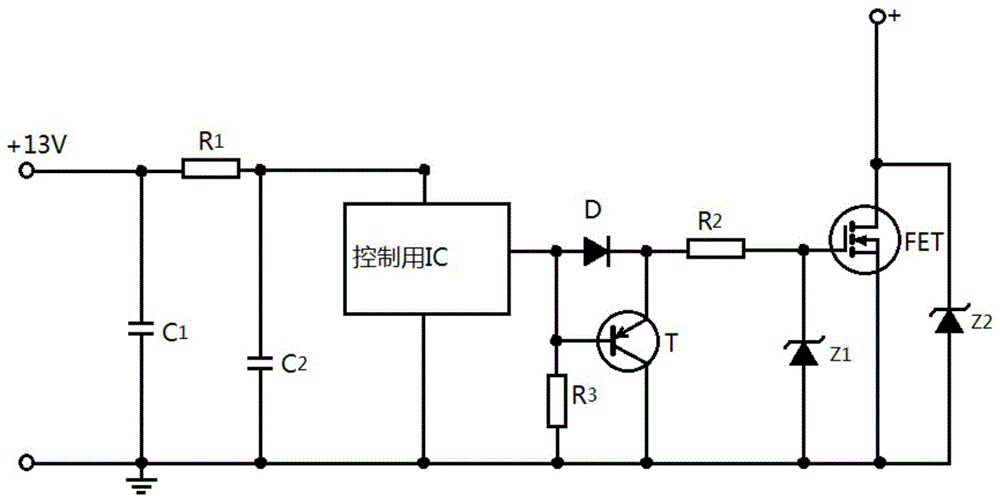
[0015] figure 1 It is a schematic diagram of the principle of the low-noise FET driving circuit equipped with a control IC of the present invention. As shown in the figure, the drive circuit includes:

[0016] The first capacitor C1, the second capacitor C2, the first resistor R1, the second resistor R2, the third resistor R3, the diode D, the first regulator Z1, the second regulator Z2, the transistor T, the field effect transistor FET, and a control IC, wherein the first end of the first capacitor C1 is connected to the first end of the first resistor R1, the first end of the first resistor R1 receives an input signal, and the second ends of the first resistor R1 are respectively Connect the first end of the second capacitor C2 to the power supply end of the control IC for providing the pulse width modulation signal of the switching power supply, and the output end of the control IC is respectively connected to the anode of the diode D, the base of the triode T and the thir...


PUM


Abstract

The invention provides a low-noise Field Effect Transistor (FET) driving circuit with a control Integrated Circuit (IC). The low-noise FET driving circuit comprises a first capacitor, a second capacitor, a first resistor, a second resistor, a third resistor, a diode, a first voltage-regulator tube, a second voltage-regulator tube, a triode, an FET and the control IC. According to the low-noise FET driving circuit, the turning on and off speed can be controlled so that a grid circuit can be protected form electrostatic damage and prevented form generating self-oscillation, noise can be reduced, and noise can be prevented from returning into a loop of a main power supply.

Description

technical field [0001] The invention relates to the driving field, more specifically, to a low-noise FET driving circuit equipped with a control IC. Background technique [0002] The basic task of the drive circuit is to convert the signal from the information electronic circuit into a signal that is added between the control terminal and the common terminal of the power electronic device to turn it on or off according to the requirements of its control target. For semi-controlled devices, only the turn-on control signal is required, while for full-control devices, both turn-on control signals and turn-off control signals are required to ensure that the devices are reliably turned on or off as required. [0003] Now, commonly used power FETs have been used as switching elements. When power FETs are used in switching power supplies, if they are directly replaced by bipolar transistor technology, they can be used almost as they are, but there are still the following problems i...

Claims


Application Information

Patent Timeline
Patent Type & Authority Patents(China)
IPC IPC(8): H03K17/687H03K17/16
Inventor 张杰马捷呼艳生刘芳宇张莹
Owner TAIYUAN UNIV OF TECH
Why Eureka
Try Eureka