Power switch tube drive circuit with adjustable switching speed of power switch tube

A power switching tube and switching speed technology, applied in electronic switches, electrical components, pulse technology, etc., can solve the problems of large current loss, small current and easy parasitic oscillation, etc., and achieve the effect of reducing loss and improving driving performance

Active Publication Date: 2017-12-26
SHANGHAI STEP ELECTRIC +1
View PDF4 Cites 0 Cited by
  • Summary
  • Abstract
  • Description
  • Claims
  • Application Information

AI Technical Summary

Problems solved by technology

[0003] At present, most power switch tube drive circuits use a gate resistor or a structure in which the turn-on resistor and the turn-off resistor are separated. No matter how large the output current of the power switch tube is, its turn-on and turn-off speeds are the same. This will lead to the problem that the loss is too large when the current is large, and the problem of parasitic oscillation is easy to occur when the current is small.

Method used


Image

  • Power switch tube drive circuit with adjustable switching speed of power switch tube

Examples


Embodiment Construction

[0017] The present invention will be further described below in conjunction with the accompanying drawings.

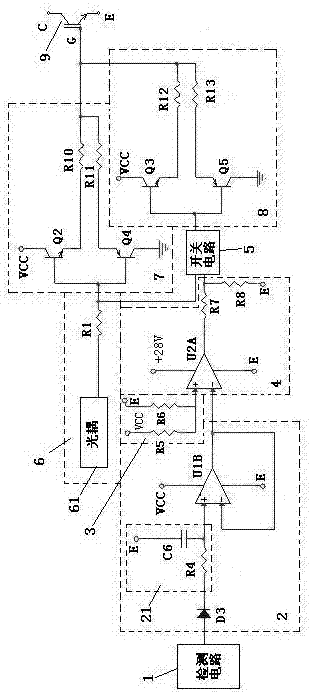
[0018] figure 1 A schematic circuit diagram of a drive circuit for a power switch tube according to an embodiment of the present invention is shown. According to an embodiment of the present invention, the power switch tube drive circuit with adjustable switching speed of the power switch tube includes a detection circuit 1, a filter circuit 2, a reference voltage generation circuit 3, a voltage comparison circuit 4, a switch circuit 5, an electrical isolation circuit 6, The first drive output circuit 7 and the second drive output circuit 8 .

[0019] The detection circuit 1 is used to generate a detection voltage signal that changes with the output current of the power switch tube 9 . figure 1 In the example, IGBT is used as the power switch tube 9, and those skilled in the art can clearly understand that, figure 1 The IGBT in can also be replaced by MOSFET. The d...


PUM


Abstract

The invention discloses a power switch tube driving circuit capable of adjusting switching speed of the power switch tube, including a detection circuit, a filter circuit, a reference voltage generation circuit, a voltage comparison circuit, a switch circuit, an electrical isolation circuit, and first and second drive output circuits. The voltage comparison circuit is used to compare the filtered detection voltage signal with the reference voltage. The electric isolation circuit is used for electrically isolating the drive control signal of the power switch tube and then outputting it. The input terminal of the first driving output circuit is connected with the output terminal of the electrical isolation circuit. The output terminals of the first and second driving output circuits are both connected to the gate of the power switch tube. The control input terminal of the switch circuit is connected with the output terminal of the voltage comparison circuit, and the first and second conduction terminals are respectively connected with the electrical isolation circuit and the output terminal of the second drive output circuit. The invention can control one driving output circuit to work or both to work simultaneously according to the output current of the power switch tube, thereby controlling the switching speed.

Description

technical field [0001] The invention relates to a drive circuit for a power switch tube. Background technique [0002] Switching characteristics are important characteristics of power switching tubes (including IGBT and MOSFET, IGBT: Insulated Gate Bipolar Transistor, that is, insulated gate bipolar transistor; MOSFET: Metal Oxide Semiconductor Field Effect Transistor, that is, metal oxide semiconductor field effect transistor). At present, in the power switch tube, the gate resistor is mostly used to charge and discharge the gate capacitor to control the switching process of the power switch tube. If the selected grid resistance is not suitable, there will be oscillation, which will increase the pulse peak of the collector or drain voltage of the power switch tube. The smaller the gate resistance, the faster the charging and discharging speed, which can reduce the switching time and switching loss, enhance the solidity of the work, and avoid the false conduction caused by ...

Claims


Application Information

Patent Timeline
Patent Type & Authority Patents(China)
IPC IPC(8): H03K17/687
Inventor 金钊江振洲邢辉程祥徐腾飞
Owner SHANGHAI STEP ELECTRIC
Why Eureka
Try Eureka