Channel resource indicating method and device

A channel resource and resource indication technology, which is applied in the field of channel resource indication methods and equipment, can solve the problems of power consumption in blind detection and the inability to know the precise position of ePDCCH, etc., and achieve the effects of reducing overhead, saving power consumption, and reducing the number of times of blind detection

Active Publication Date: 2014-01-15
TONGDING INTERCONNECTION INFORMATION CO LTD
View PDF4 Cites 14 Cited by
  • Summary
  • Abstract
  • Description
  • Claims
  • Application Information

AI Technical Summary

Problems solved by technology

[0011] 1) The existing three types of PDSCH time-frequency resource indication methods can only be indicated at the RB or RBG level, and ePDCCH can only occupy part of the CCEs in one RB, that is, one RB can be multiplexed by ePDCCHs of multiple UEs Therefore, the existing resource indicati

Method used


Image

  • Channel resource indicating method and device
  • Channel resource indicating method and device
  • Channel resource indicating method and device

Examples


Example Embodiment

[0036] The technical solutions in the embodiments of the present invention will be clearly and completely described below in conjunction with the accompanying drawings in the embodiments of the present invention. Obviously, the described embodiments are only a part of the embodiments of the present invention, rather than all the embodiments. Based on the embodiments of the present invention, all other embodiments obtained by those of ordinary skill in the art without creative work shall fall within the protection scope of the present invention.
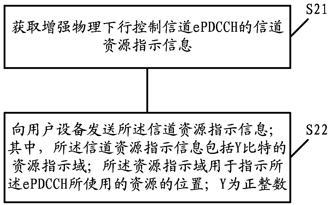
[0037] See figure 2 , This embodiment provides a channel resource indication method, including the following steps:

[0038] S21. Obtain channel resource indication information of the enhanced physical downlink control channel ePDCCH.

[0039] S22. Send the channel resource indication information to the user equipment.

[0040] Wherein, the channel resource indication information includes a Y-bit resource indication field; the resource indic...


PUM


Abstract

The invention discloses a channel resource indicating method. The method comprises the steps that the channel resource indicating information of an ePDCCH is obtained; the channel resource indicating information is transmitted to user equipment; the channel resource indicating information comprises resource indicating fields of y bits; the resource indicating fields are used for indicating the position of resources used by the ePDCCH; y is a positive integer. The invention further discloses a base station and the user equipment. The channel resource indicating method and device can reduce the cost of control commands used for indicating the ePDCCH, and the power consumption of the user equipment is saved.

Description

technical field [0001] The present invention relates to the technical field of communication, in particular to a channel resource indication method and equipment. Background technique [0002] 3GPP (3rd Generation Partnership Project, 3rd Generation Partnership Project) LTE-ARel-10 / 11 (Long Term Evolution-Advance Rel-10 / 11, version 10 / 11 of Advanced Long-term Evolution) is an enhancement of LTE Rel-8 technology , the LTE-A system has higher bandwidth requirements than the LTE system, and supports a peak data rate of up to 1 Gbits / s. In order to meet the bandwidth requirements of LTE-A, the LTE-A system uses CA (Carrier Aggregation, Carrier Aggregation) technology as a method to expand system bandwidth, and extensively uses MIMO (Multiple Input Multiple Output, also known as multiple Antenna technology) enhancement technology and adaptive technology to improve data rate and system performance. [0003] In systems prior to LTE-A Rel-11, the base station carries scheduling gr...

Claims


Application Information

Patent Timeline
IPC IPC(8): H04W72/04
CPCH04W28/06H04W52/0229Y02D30/70H04W72/23
Inventor 张兴炜
Owner TONGDING INTERCONNECTION INFORMATION CO LTD
Why Eureka
Try Eureka