Radiation treatment delivery system with ring gantry

A radiotherapy, annular gantry technology, used in radiotherapy, treatment, instruments for radiological diagnosis, etc., can solve the problems of patient collision, collision, etc.

Active Publication Date: 2014-01-15
爱可瑞公司
View PDF11 Cites 24 Cited by
  • Summary
  • Abstract
  • Description
  • Claims
  • Application Information

AI Technical Summary

Problems solved by technology

However, at least one difficulty that arises is that the LINAC could potentially collide or nearly collide wi

Method used


Image

  • Radiation treatment delivery system with ring gantry
  • Radiation treatment delivery system with ring gantry
  • Radiation treatment delivery system with ring gantry

Examples


Embodiment Construction

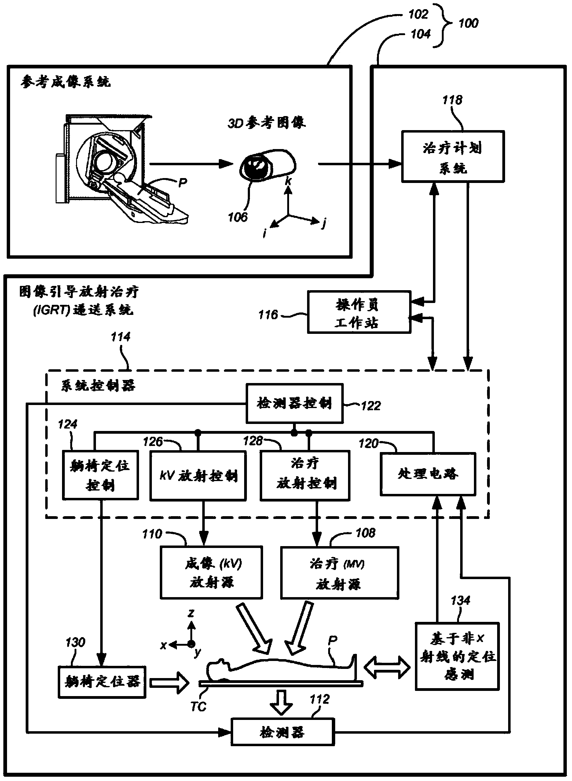
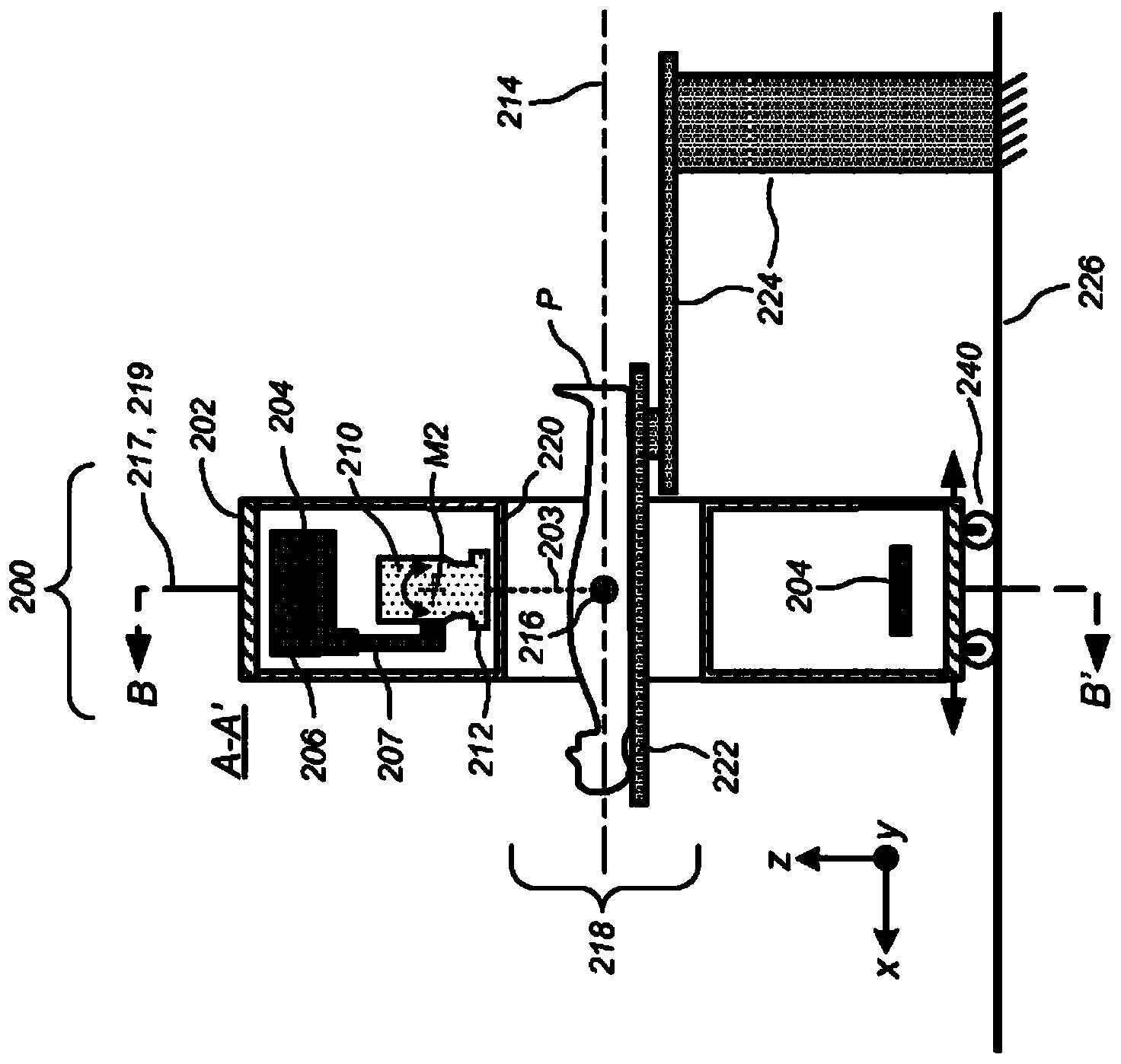
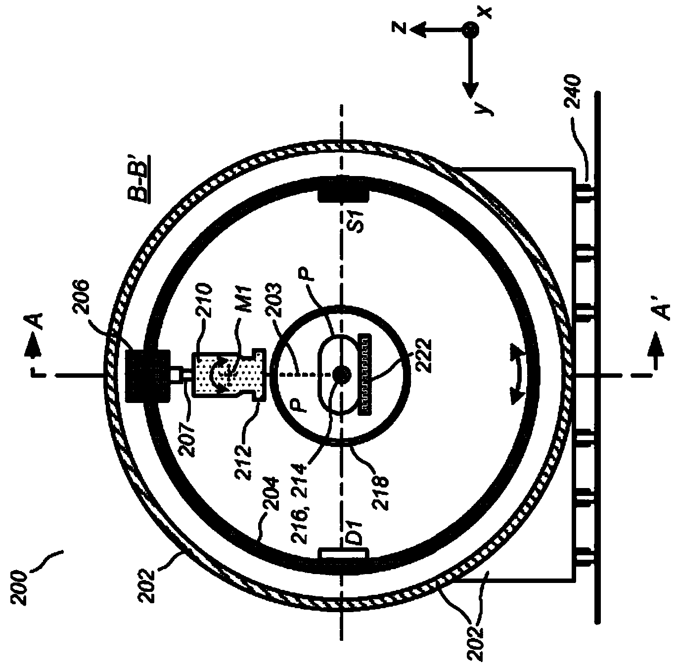
[0046] Systems, methods, and related computer program products for image-guided radiation therapy (IGRT) are described further below, including image-guided radiation therapy (IGRT) systems that provide an advantageous combination of: high mechanical stability, radiation Versatility during delivery, outdoor configuration, and the ability to keep the patient stationary between the time of (i) pre-treatment imaging and / or setup imaging and (ii) treatment delivery including in-treatment imaging. In a preferred embodiment, there is provided a radiotherapy apparatus comprising: an annular gantry having a central opening; a radiotherapy head connected to the annular gantry a frame and rotatable at least 180 degrees arc around the central opening; and a stage translation mechanism configured to translate the annular stage in a direction extending through the longitudinal axis of the central opening . In a preferred embodiment, the annular gantry is contained within an annular gantry...


PUM


Abstract

Systems, methods, and related computer program products for image-guided radiation treatment (IGRT) are described. For one preferred embodiment, an IGRT apparatus is provided comprising a ring gantry having a central opening and a radiation treatment head coupled to the ring gantry that is rotatable around the central opening in at least a 180 degree arc. For one preferred embodiment, the apparatus further comprises a gantry translation mechanism configured to translate the ring gantry in a direction of a longitudinal axis extending through the central opening. Noncoplanar radiation treatment delivery can thereby be achieved without requiring movement of the patient. For another preferred embodiment, an independently translatable 3D imaging device distinct from the ring gantry is provided for further achieving at least one of pre-treatment imaging and setup imaging of the target tissue volume without requiring movement of the patient.

Description

[0001] Cross References to Related Applications [0002] This application claims the benefit of U.S. Provisional Application No. 61 / 434,824, filed January 20, 2011, and U.S. Application Nos. 13 / 088,289 and 13 / 088,321, both filed April 15, 2011, all of which are for all purposes Incorporated herein by reference. The subject matter of this patent specification is related to that of the following commonly assigned applications: U.S. Application No. 13 / 033,571, filed February 23, 2011; U.S. Application No. 13 / 033,584, filed February 23, 2011; International Application No. PCT / US11 / 25936, filed June 8, 2010; U.S. Provisional Application No. 61 / 352,637, filed June 8, 2010; U.S. Provisional Application No. 61 / 371,732, filed August 8, 2010; and August 8, 2010 Filed U.S. Provisional Application No. 61 / 371,733. The patent applications cited above are hereby incorporated by reference in their entirety. technical field [0003] This patent specification relates to the use of radiation ...

Claims


Application Information

Patent Timeline
IPC IPC(8): A61N5/10A61N5/00
CPCA61B5/055A61B6/035A61B6/0478A61B6/102A61B6/4435A61B6/4441A61B6/4447A61B6/4458A61N5/10A61N5/1048A61N5/1081A61N5/1082A61N2005/1061A61N2005/1055A61N2005/0633A61N5/1049A61N5/1067A61N5/1045A61N2005/1063
Inventor C·R·小毛雷尔E·P·林德奎斯特
Owner 爱可瑞公司
Why Eureka
Try Eureka