Floating core-pulling mechanism for pipe fitting forming

A core-pulling mechanism and pipe fitting technology, applied in forming tools, metal processing equipment, peeling devices, etc., can solve the problems of long core-pulling stroke, high manufacturing cost, low production efficiency, etc., and achieve the effect of stamping and forming

Active Publication Date: 2014-01-22
SHANGHAI HUIZHONG AUTOMOTIVE MFG
View PDF8 Cites 4 Cited by
  • Summary
  • Abstract
  • Description
  • Claims
  • Application Information

AI Technical Summary

Problems solved by technology

The forming of the tubular longitudinal arm generally adopts the hydraulic core-pulling method, which has the disadvantages of long core-pulling stroke, large number of moulds, high manufacturing cost, and low production efficiency. The high output of the automotive industry requires an integrated multi-station mold , a new process method with automatic core pulling, fast beats and less molds

Method used


Image

  • Floating core-pulling mechanism for pipe fitting forming
  • Floating core-pulling mechanism for pipe fitting forming
  • Floating core-pulling mechanism for pipe fitting forming

Examples


Embodiment Construction

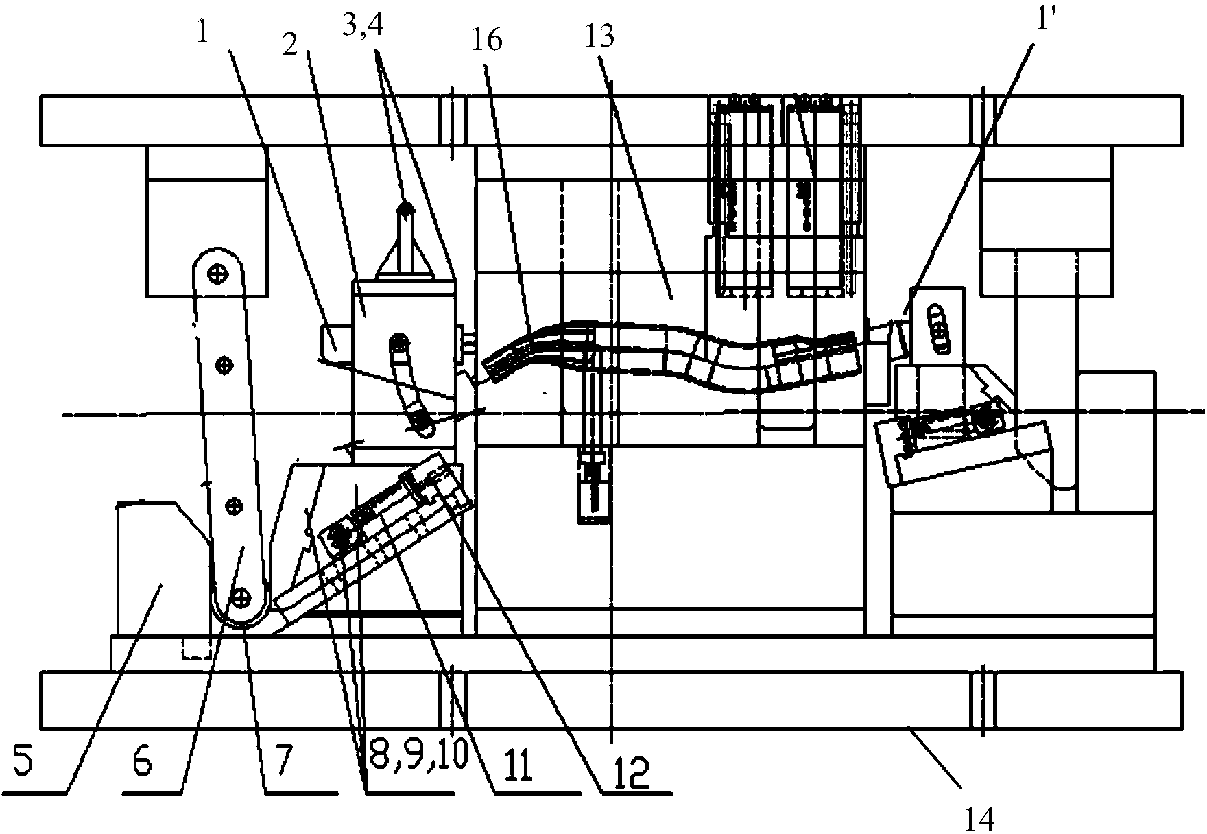
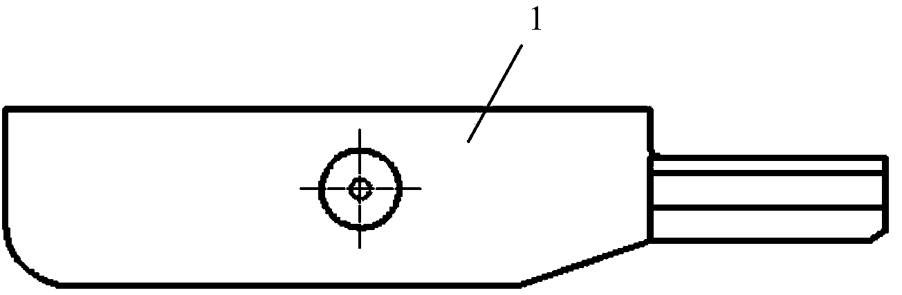
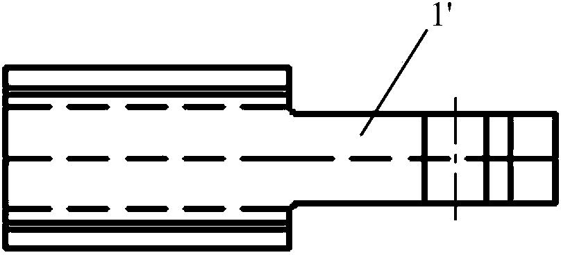
[0027] exist figure 1 The combined multi-position pipe fitting forming mold uses two sets of pipe forming floating core-pulling mechanisms to control the entry and exit of the floating core-pulling for the two sections of the formed pipe respectively. In the following description, the main description figure 1 The structure and working principle of the pipe forming floating core-pulling mechanism on the left side in the middle are basically suitable for the pipe forming floating core-pulling mechanism on the right. The difference between the two is mainly that the core-pulling action is reversed and the installation position is different. In addition if figure 2 As shown, the floating core-pulling 1 on the left is a flat rod, such as image 3 As shown, the floating core pulling 1' on the right is a round mandrel.

[0028] Such as figure 1 As shown, the pipe forming floating core-pulling mechanism can be divided into upper, middle and lower parts, namely the upper die wedg...


PUM


Abstract

Provided is a floating core-pulling mechanism for pipe fitting forming. The floating core-pulling mechanism for pipe fitting forming can be used for replacing a traditional long-stroke hydraulic core-pulling structure. According to the floating core-pulling mechanism for pipe fitting forming, a guide groove is formed in a guide support, the guide groove and a floating core-pulling portion are in sliding fit through a guide pin, a reset spring is assembled between a base body and the floating core-pulling portion, a sliding wedge supports the guide support, a wedge base is provided with a slope, the sliding wedge and the slope are in sliding fit, a limiting link stopper is arranged corresponding to the sliding wedge, a pinch roller is connected with the lower end of a connecting rod, the upper end of the connecting rod is connected with an upper die, namely a movable die, of a die, when the connecting rod moves downwards, the sliding wedge and the limiting link stopper can be separated through the pinch roller, the connecting rod can enter the position between the sliding wedge and the limiting link stopper to push the sliding wedge, the limiting link stopper and the wedge base are arranged on a lower die, namely a stationary die, of the die, and the nature state of a telescopic device is the state that the size of a gap between the sliding wedge and the limiting link stopper is kept to be smaller than the outer diameter of the pinch roller.

Description

technical field [0001] The invention relates to a floating core-pulling mechanism for forming pipe fittings. Background technique [0002] The chassis of the rear axle of the car has a torsion beam structure design, using cross beams and longitudinal arms welded. The forming of the tubular longitudinal arm generally adopts the hydraulic core-pulling method, which has the disadvantages of long core-pulling stroke, large number of moulds, high manufacturing cost, and low production efficiency. The high output of the automotive industry requires an integrated multi-station mold , Automatic core-pulling, fast beat, new process method with less molds. The bottleneck problem is the integrated design of the automatic core-pulling structure of the pipe fitting mold. Contents of the invention [0003] The purpose of the present invention is to provide a pipe forming floating core-pulling mechanism to replace the traditional long-stroke hydraulic core-pulling structure. [0004] ...

Claims


Application Information

Patent Timeline
Patent Type & Authority Applications(China)
IPC IPC(8): B21D37/12B21D45/00
Inventor 桂俊宏
Owner SHANGHAI HUIZHONG AUTOMOTIVE MFG
Why Eureka
Try Eureka