Sensor installation structure and installation method of automatic servo press

An installation structure and automatic servo technology, applied in the direction of instruments, measuring devices, force/torque/power measuring instruments, etc., can solve problems such as equipment damage and deviation, achieve real-time reading, ensure concentricity, and facilitate zero adjustment Effect

Active Publication Date: 2016-01-20
上海新暴威电子科技有限公司
View PDF6 Cites 0 Cited by
  • Summary
  • Abstract
  • Description
  • Claims
  • Application Information

AI Technical Summary

Problems solved by technology

In the mainstream design scheme, the main problem faced by the pressure sensor in the automatic servo press is the concentricity of the sensor and its auxiliary mechanical structure. Once the concentricity deviates, the entire measurement data will inevitably deviate, and the equipment has been relatively different for a long time. It is very likely to cause damage to the device itself, resulting in a permanent deviation until it is scrapped.

Method used


Image

  • Sensor installation structure and installation method of automatic servo press

Examples


Embodiment Construction

[0010] The present invention will be further described below in conjunction with the accompanying drawings and embodiments.

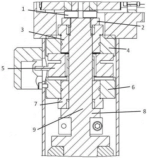
[0011] Such as figure 1 As shown, a sensor installation structure of an automatic servo press machine includes a ball screw 9, a lower bearing 7, a lower bearing seat 6, a pressure sensor 5, an upper bearing seat 4, an upper bearing 3, a bearing lock nut 2 and a locking nut1.

[0012] The pressure sensor 5 is fixed in the middle by the upper and lower bearing seats 4, 6, and the upper and lower bearing seats 4, 6 are respectively fixed with upper and lower bearings 3, 7, and the center of the upper and lower bearings 3, 7 is inserted and installed On the ball screw 9, one end of the lower bearing 7 is close to the annular fastener 8 on the ball screw 9, and one end of the upper bearing 3 is fixed by a bearing lock nut 2, and a lock nut 1 is added to ensure that it will not loose.

[0013] When installing, first put the lower bearing 7 and the lower b...


PUM


Abstract

The invention relates to a structure and method for installing a sensor of an automatic servo pressing fit machine. The upper end of a ball screw is connected with an upper bearing seat through an upper bearing; the lower end of the ball screw is connected with a lower bearing seat through a lower bearing. The pressure sensor is coaxially installed at the position, between the upper bearing seat and the lower bearing seat, of the ball screw. A bearing locking nut and a locking nut are screwed at the position, above the upper bearing, of the ball screw. The upper bearing is adjusted to be locked through the bearing locking nut. The lower end face of the lower bearing closely abuts against an annular fastener on the ball screw. The initial pressure value of the pressure sensor can be controlled by adjusting the annular nuts. By means of the structure, when the screw rotates under the driving of an external motor, upward force is exerted to the ball screw, passes through the annular fastener on the screw to be transmitted to the lower bearing, then is transmitted to the lower bearing seat from the lower bearing, and then is reflected on the pressure sensor, and accordingly real-time pressure data can be read.

Description

technical field [0001] The invention relates to an automatic servo pressing machine, in particular to a sensor installation structure and installation method in the automatic servo pressing machine. Background technique [0002] At present, automatic servo presses are not common in China, and are more common in Europe, America and Japan. In the mainstream design scheme, the main problem faced by the pressure sensor in the automatic servo press is the concentricity of the sensor and its auxiliary mechanical structure. Once the concentricity deviates, the entire measurement data will inevitably deviate, and the equipment has been relatively different for a long time. Actions in the state of the heart are very likely to cause damage to the equipment itself, resulting in permanent deviations and even scrapping. [0003] The solution of the present invention is dedicated to designing a simple and effective concentricity control structure suitable for the installation of the pres...

Claims


Application Information

Patent Timeline
Patent Type & Authority Patents(China)
IPC IPC(8): B23P19/02
CPCB23P19/02G01L5/0085
Inventor 潘延庆
Owner 上海新暴威电子科技有限公司
Why Eureka
Try Eureka