Pipe bridge hanging system

A pipeline bridge and saddle technology, applied in bridges, bridge parts, bridge applications, etc., can solve the problems of long cycle, high strength and specification requirements of steel cables, large space for temporary towers and temporary ground anchors, etc.

Active Publication Date: 2014-01-22
CHINA PETROLEUM & CHEM CORP +1
View PDF6 Cites 9 Cited by
  • Summary
  • Abstract
  • Description
  • Claims
  • Application Information

AI Technical Summary

Problems solved by technology

[0004] The above construction techniques have the following deficiencies: (1) The cost of building two temporary towers is relatively high, and the cycle is relatively long, which increases labor costs, material costs and time costs; (2) Many construction sites do not have the conditions to build temporary towers. As a result, it is impossible to replace the steel cables, and it is even more impossible to replace the pipeline without continuous transmission; (3) The span between the temporary towers is larger than that of the original towers, and the erection of the temporary steel cables is difficult and risky. The strength and specification requirements are higher, and the construction cost is high; (4) Temporary towers and temporary ground anchors occupy a large space, and the construction will cause great damage to the environment; (5) In addition to the replacement of new steel cables, temporary steel (6) The load of the pipeline bridge is first transferred from the single steel cable to the temporary steel cable, and then transferred from the temporary steel cable to the new steel cable. At least two load transfers have taken place, which increases the safety risk; ⑺The on-site construction period is long, which increases the safety hazard to the normal transportation of the pipeline

Method used


Image

  • Pipe bridge hanging system
  • Pipe bridge hanging system
  • Pipe bridge hanging system

Examples


Embodiment Construction

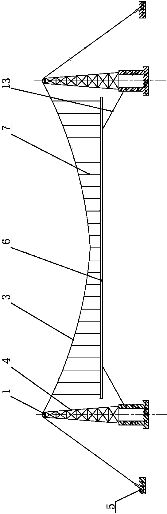
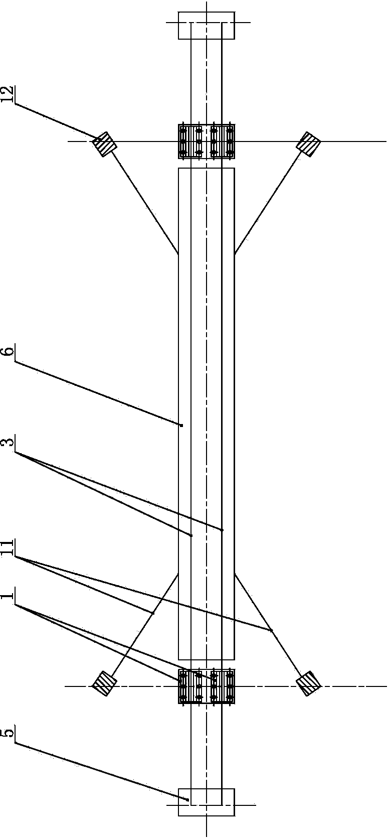
[0031] Such as figure 1 , figure 2 As shown, the suspension system of the pipeline bridge of the present invention comprises a tower 4 positioned on both banks of the river and a pipeline bridge 6 between the two towers. It includes two ground anchor screw rods 5a, the two ground anchor screw rods 5a are parallel to each other and the upper ends point to the saddle device, and the middle parts of the two ground anchor screw rods 5a are jointly screwed with a cable-anchor connecting block 5b.

[0032]A saddle device is respectively fixed on the top platform of each tower frame 4, and a plurality of suspenders 7 are respectively connected to both sides of the pipeline bridge 6 in the width direction, and the upper parts of each suspender 7 are respectively fixedly connected with corresponding steel cables, and the two steel cables are in the The upper part of the river is in the shape of a suspension cable with a low middle and high ends.

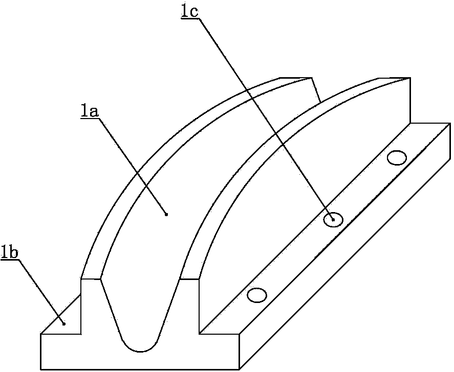
[0033] The saddle device includes a...


PUM


Abstract

The invention relates to a pipe bridge hanging system. Saddle devices are respectively fixed on platforms of the tops of towers, each saddle device comprises an upper saddle and a lower saddle, the upper saddles and the lower saddles are overlaid, the two ends of a steel rope are respectively embedded in saddle-shaped guide grooves of the lower saddles and downwards fixed to the middles of rope anchor connecting blocks, each upper saddle comprises an upper saddle body, a main rope hanging lug and a back rope hanging lug, the main rope hanging lugs are connected to the middles of one ends, facing a river, of the upper saddle bodies, the two back rope hanging lugs are respectively connected to the two sides of one end, opposite to the river, of the upper saddle bodies, the lower end faces of the two sides in the width direction of the upper saddle bodies are all planes and respectively installed on the flange edges of the lower saddles, the two sides in the width directions of the upper saddle bodies are respectively provided with an upper saddle bolt hole coaxial with lower saddle bolt holes, the upper saddles and the lower saddles are jointly fixed on the platforms of the tops of the towers through bolts, main ropes are connected between main rope hanging lugs, and back ropes are respectively connected between the back rope hanging lugs and ground anchor threaded rods. When steel ropes of the pipe bridge hanging system are replaced, the project time limit is short, and the safety performance is good.

Description

technical field [0001] The invention relates to a pipeline bridge, in particular to a pipeline bridge suspension system used for pipelines crossing rivers, canyons and the like. Background technique [0002] Pipelines crossing rivers, canyons, etc. are often in the form of pipeline suspension bridges. The pipeline is supported on a horizontal pipeline bridge. The two sides of the width direction of the pipeline bridge are respectively connected with suspenders. Multiple suspenders are evenly distributed along the length of the pipeline bridge. When the bridge is hoisted, the upper part of each suspender is fixedly connected with the steel cable. The steel cable is suspended above the river surface in the form of a suspension cable with a low middle and high ends. Towers are respectively built on both sides of the river, and a pair of towers are respectively fixed on the top platforms of the two towers. The saddle, the steel cable turns downward through the saddle and the end...

Claims


Application Information

Patent Timeline
Patent Type & Authority Applications(China)
IPC IPC(8): E01D18/00E01D19/16E01D19/14
Inventor 汪飞李熙岩王健恺张洪军刘军
Owner CHINA PETROLEUM & CHEM CORP
Why Eureka
Try Eureka