Full-automatic cleaning window and control circuit and working mode thereof

A control circuit, fully automatic technology, used in windows/doors, cleaning equipment, window cleaning, etc., can solve the problems of difficult cleaning, unsightly, heavy workload, etc.

Active Publication Date: 2014-01-22
JINLING INST OF TECH
View PDF8 Cites 4 Cited by
  • Summary
  • Abstract
  • Description
  • Claims
  • Application Information

AI Technical Summary

Problems solved by technology

[0003]At present, there are more and more skyscrapers in cities, how to maintain skyscraper components and exterior walls conveniently has become the focus of attention, so the window glass of high-rise buildings needs to be cleaned. The volume is huge, and it is very difficult to clean, so some people think of using the motor to drive the brush to clean, but there are still many problems in this way, such as how the brush contacts with the cleaning liquid. Building windows are arranged in rows, so it is very difficult to get each brush in contact with the cleaning liquid, and the brushes are exposed outside, which is very unsightly

Method used


Image

  • Full-automatic cleaning window and control circuit and working mode thereof
  • Full-automatic cleaning window and control circuit and working mode thereof
  • Full-automatic cleaning window and control circuit and working mode thereof

Examples


Embodiment Construction

[0043] Below in conjunction with accompanying drawing and embodiment the invention is described in detail:

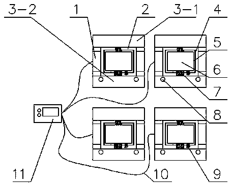
[0044] The present invention is a fully automatic window cleaning structure, control circuit and working method. The mechanism can realize the function of automatically cleaning windows at regular intervals and pressing the button to clean windows at any time according to needs, thereby greatly reducing the work difficulty of cleaning personnel.

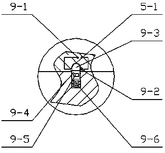
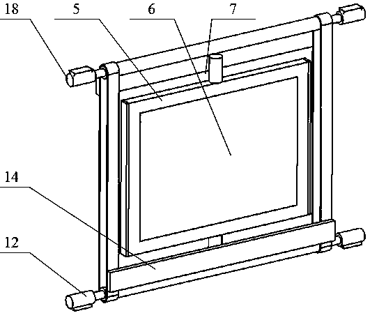
[0045] As a specific embodiment of the present invention, the present invention provides a schematic diagram such as figure 1 As shown, the internal mechanism such as image 3 As shown, the side view is as Figure 5 As shown, each of the fully automatic cleaning windows is connected to the controller 11 through a connection line 10, and the fully automatic cleaning windows include a window bracket 1, a mounting bracket 2, a U-shaped cover plate, a movable window frame 5, a glass 6, a locking Mechanism 9, rotating shaft 12, ...


PUM


Abstract

A full-automatic cleaning window comprises a window support, an installing support, a U-shaped cover plate, a movable window frame, glass, rotating shafts, a transmission belt, brushes, a motor and a movable door, the installing support is arranged inside the window support, the glass is arranged inside the movable window frame, the movable window frame is installed inside an installing support groove through revolving shafts, the two rotating shafts are arranged on the upper portion and the lower portion of the installing support respectively, the end portions of the rotating shafts are connected with a motor output shaft, the two outer sides of the transmission belt are respectively provided with one brush, a motor amphenol connector is connected with a controller through a connecting wire, an upper U-shaped cover plate body is arranged at the upper end of the window support, a lower U-shaped cover plate body is arranged at the lower end of the window support, a hole is formed in one side of the lower U-shaped cover plate body, an end cover is arranged on the hole of the lower U-shaped cover plate body, two installing grooves are formed inside the lower U-shaped cover plate body, and the movable door is installed inside the installing grooves of the lower U-shaped cover plate body through a supporting spring. The purposes that a window can be regularly and automatically cleaned and the window can be cleaned at any time when a user presses a button can be achieved according to needs, and therefore work difficulty of cleaning staff can be greatly reduced.

Description

technical field [0001] The invention relates to the field of window cleaning equipment, in particular to a structure, control circuit and working method of fully automatic window cleaning. [0002] Background technique [0003] At present, there are more and more skyscrapers in cities, and how to maintain skyscraper components and exterior walls conveniently has become the focus of attention. Therefore, it is a huge workload to clean the window glass of high-rise buildings, and it is very difficult to clean, so some people think of using motors to drive However, there are still many problems in this way, such as how the brushes are in contact with the cleaning liquid. Although there is no need for people to clean them outside, because the windows of high-rise buildings are in rows, each brush must be cleaned. It is very difficult to contact with the cleaning liquid, and the brush is exposed, which is very unsightly. [0004] Contents of the invention [0005] In view of...

Claims


Application Information

Patent Timeline
Patent Type & Authority Applications(China)
IPC IPC(8): E06B7/28A47L1/02E06B3/40E06B7/22E05C1/12
Inventor 高素美鞠全勇牟福元顾恒杨庆凤
Owner JINLING INST OF TECH
Why Eureka
Try Eureka