Membrane type automobile clutch

A clutch and diaphragm type technology, which is applied in the field of auto parts, can solve the problems of easy rupture of the inner support ring, troublesome and laborious prying of the tongue, and large disassembly workload, so as to improve the safety and reliability, and achieve a simple structure. , the effect of high production efficiency

Inactive Publication Date: 2014-01-22
解良川
View PDF5 Cites 3 Cited by
  • Summary
  • Abstract
  • Description
  • Claims
  • Application Information

AI Technical Summary

Problems solved by technology

[0002] The existing diaphragm type automobile clutch is composed of a pressure plate, a clutch cover, a diaphragm, an inner support ring and an outer support ring. The clutch cover is provided with several circumferentially evenly distributed flaps. When installing the inner support ring, the clutch cover is The inner support ring is installed between the clutch cover and the diaphragm by bending the tongue. With such a structure, there are the following problems: 1. The assembly workload is large and the assembly efficiency is low; 2. During use, the inner support ring The ring is prone to breakage, and the inner support ring must be removed for replacement. However, when replacing the inner support ring, it is necessary to pry apart several evenly distributed circumferentially bent tongues on the clutch cover one by one, and then remove the broken inner support ring. In this replacement method, since the tongue flap of the clutch cover is thicker, it is very troublesome and laborious to pry off the tongue flap, and the workload of disassembly is large. The tongue will be greatly deformed when it is pried open, it cannot be reused, and a new clutch cover must be replaced, thereby increasing the maintenance cost

Method used


Image

  • Membrane type automobile clutch
  • Membrane type automobile clutch
  • Membrane type automobile clutch

Examples


Embodiment Construction

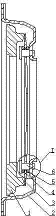
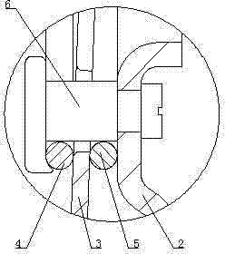
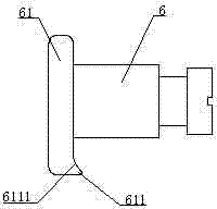
[0009] see Figure 1 to Figure 3 , the present invention includes a pressure plate 1, a clutch cover 2, a diaphragm 3, an inner support ring 4 and an outer support ring 5, and also includes several diaphragm rivets 6 uniformly distributed in the circumferential direction, and the left end of the diaphragm rivet 6 is provided with a shoulder 61. On the right end surface of the shoulder 61, there is a pointed protrusion 611 with tooth tip facing right. The pointed protrusion 611 is provided with a concave arc surface 6111. The diaphragm rivet 6 is sequentially arranged from left to Right connect the inner supporting ring 4 , the diaphragm 3 , the outer supporting ring 5 and the clutch cover 2 , and make the concave arc surface 6111 on the diaphragm rivet 6 closely adhere to the inner supporting ring 4 . The radius of the concave arc surface 6111 on the diaphragm rivet 6 is slightly larger than the radius of the steel wire of the inner supporting ring 4 .


PUM


Abstract

The invention discloses a membrane type automobile clutch which comprises a pressing plate (1), a clutch cover (2), a membrane (3), an inner supporting ring (4) and an outer supporting ring (5). The membrane type automobile clutch is characterized in that the membrane type automobile clutch further comprises a plurality of membrane rivets (6) which are evenly distributed in the circumferential direction, a circular bead (61) is arranged at the left end of each membrane rivet (6), a pointed protrusion (611) with a tooth point facing rightwards is arranged on the right end face of each circular bead (61), each pointed protrusion (611) is provided with a concave arc face (6111), the inner supporting ring (4), the membrane (3), the outer supporting ring (5) and the clutch cover (2) are sequentially connected together from left to right through the membrane rivets (6), and the concave arc faces (6111) on the membrane rivets (6) are tightly attached to the inner supporting ring (4); the radius of the concave arc face (6111) on each membrane rivet (6) is slightly larger than that of a steel wire of the inner supporting ring (4). The membrane type automobile clutch is simple in structure, easy to assemble and disassemble, convenient to repair, high in production efficiency, low in cost, safe and reliable.

Description

technical field [0001] The invention relates to auto parts, in particular to a diaphragm type auto clutch. Background technique [0002] The existing diaphragm type automobile clutch is composed of a pressure plate, a clutch cover, a diaphragm, an inner support ring and an outer support ring. The clutch cover is provided with several circumferentially evenly distributed flaps. When installing the inner support ring, the clutch cover is The inner support ring is installed between the clutch cover and the diaphragm by bending the tongue. With such a structure, there are the following problems: 1. The assembly workload is large and the assembly efficiency is low; 2. During use, the inner support ring The ring is prone to breakage, and the inner support ring must be removed for replacement. However, when replacing the inner support ring, it is necessary to pry apart several evenly distributed circumferentially bent tongues on the clutch cover one by one, and then remove the brok...

Claims


Application Information

Patent Timeline
IPC IPC(8): F16D13/70
Inventor 解良川
Owner 解良川
Why Eureka
Try Eureka