Hybrid permanent magnet type electric rotating machine and manufacturing method thereof

a permanent magnet type, electric rotating machine technology, applied in the direction of magnetism, instruments, horology, etc., can solve the problems of affecting the overall generating vibration and noise, and deteriorating positioning accuracy, so as to reduce the total cost of the electric rotating machine, reduce the total cost, and reduce the effect of electric power

Inactive Publication Date: 2007-08-30
NIDEC SERVO CORP
View PDF11 Cites 3 Cited by
  • Summary
  • Abstract
  • Description
  • Claims
  • Application Information

AI Technical Summary

Benefits of technology

[0017]Still further, the magnetizing device that is provided with the above-mentioned yoke can magnetize the magnet materials by smaller electric power as compared with the conventional magnetizing device that is provided with an air-core coil.
[0018]Since the assembled electric rotating machine is provided with the two sets of rotor units each of which includes the permanent magnet, the magnetic flux density required of each permanent magnet becomes smaller than that of a permanent magnet of the conventional rotor unit that has a single permanent magnet. Therefore, the assembled electric rotating machine can use a magnet formed from low cost magnet material such as a bonded magnet and a ferrite magnet. This can decrease the total cost of the electric rotating machine as compared with the cost of the conventional electric rotating machine that uses a magnet formed from high cost magnet material such as a neodymium magnet. Since the assembled electric rotating machine is provided with the two sets of rotor units, unbalance torque does not generate even if the stator has the small number of the main poles, which can reduce vibration and noise due to the unbalanced torque and can facilitate the assembling work of the stator due to simple windings.

Problems solved by technology

However, in the above-mentioned conventional structure (a full-main-pole structure), the stator has many main poles, and the manufacturing cost becomes high.
This generates an unbalanced electromagnetic force due to the attraction forces in the radial direction (couple of forces due to so-called side pull), which generates vibration and noise, and deteriorates positioning accuracy.
Although the motor structure disclosed in U.S. Pat. No. 6,781,260 requires that two permanent magnets are magnetized in the opposite polarities, an appropriate magnetization method has not been established.
However, when a conventional magnetizing device with an air-core coil tries to magnetize two permanent magnets at the same time, the permanent magnets are insufficiently magnetized because the magnetic fluxes for magnetization repel to each other.
On the other hand, when the conventional magnetizing device tries to magnetize two permanent magnets one by one with time difference, the magnetic flux for magnetizing the permanent magnet of one rotor unit leaks to the other rotor unit.
In such a method, however, since the permanent magnet attracts iron powder and dust during the assembling, the assembling of an electric rotating machine becomes difficult, and the reliability of the completed electric rotating machine decreases.

Method used


Image

  • Hybrid permanent magnet type electric rotating machine and manufacturing method thereof
  • Hybrid permanent magnet type electric rotating machine and manufacturing method thereof
  • Hybrid permanent magnet type electric rotating machine and manufacturing method thereof

Examples


first embodiment

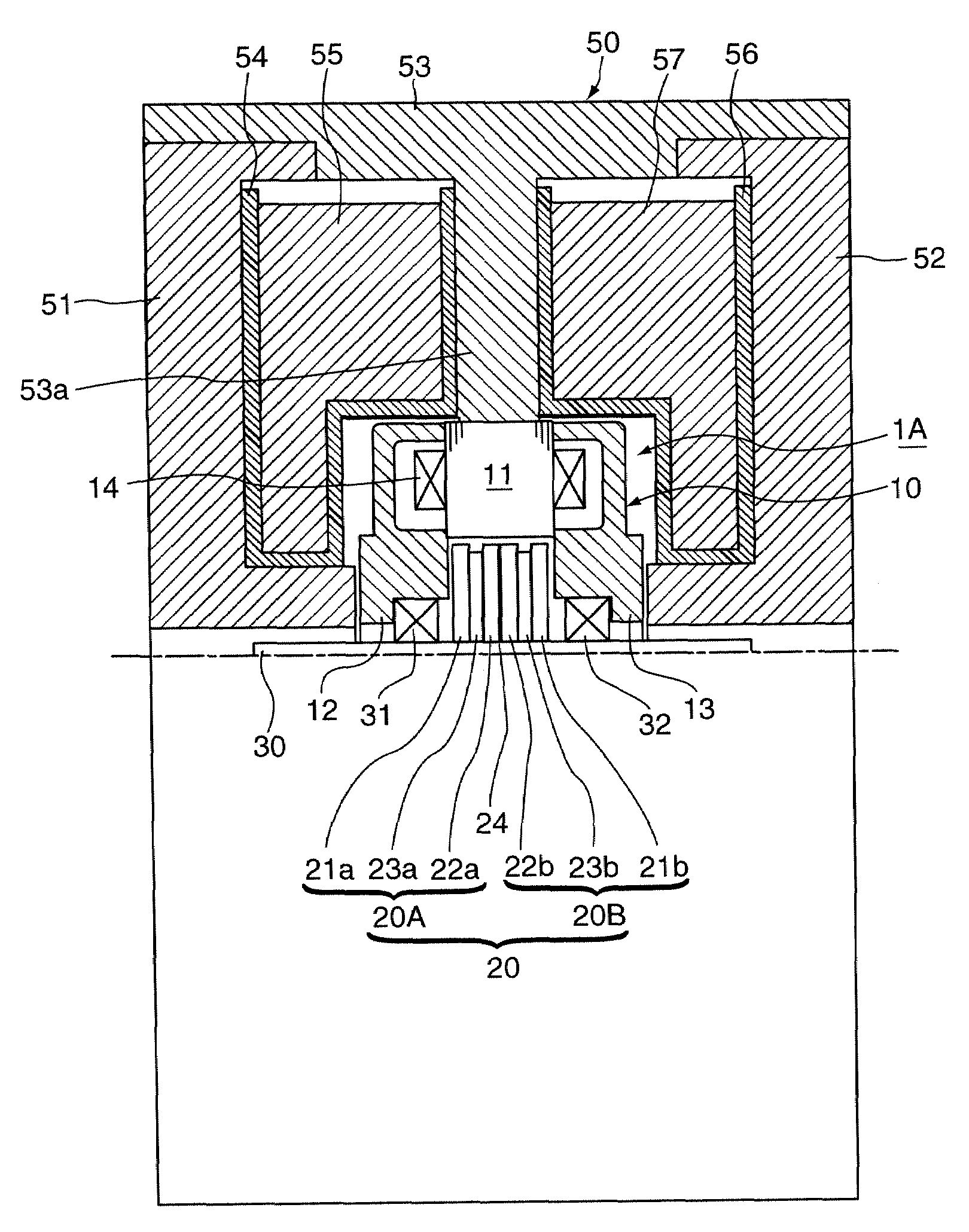
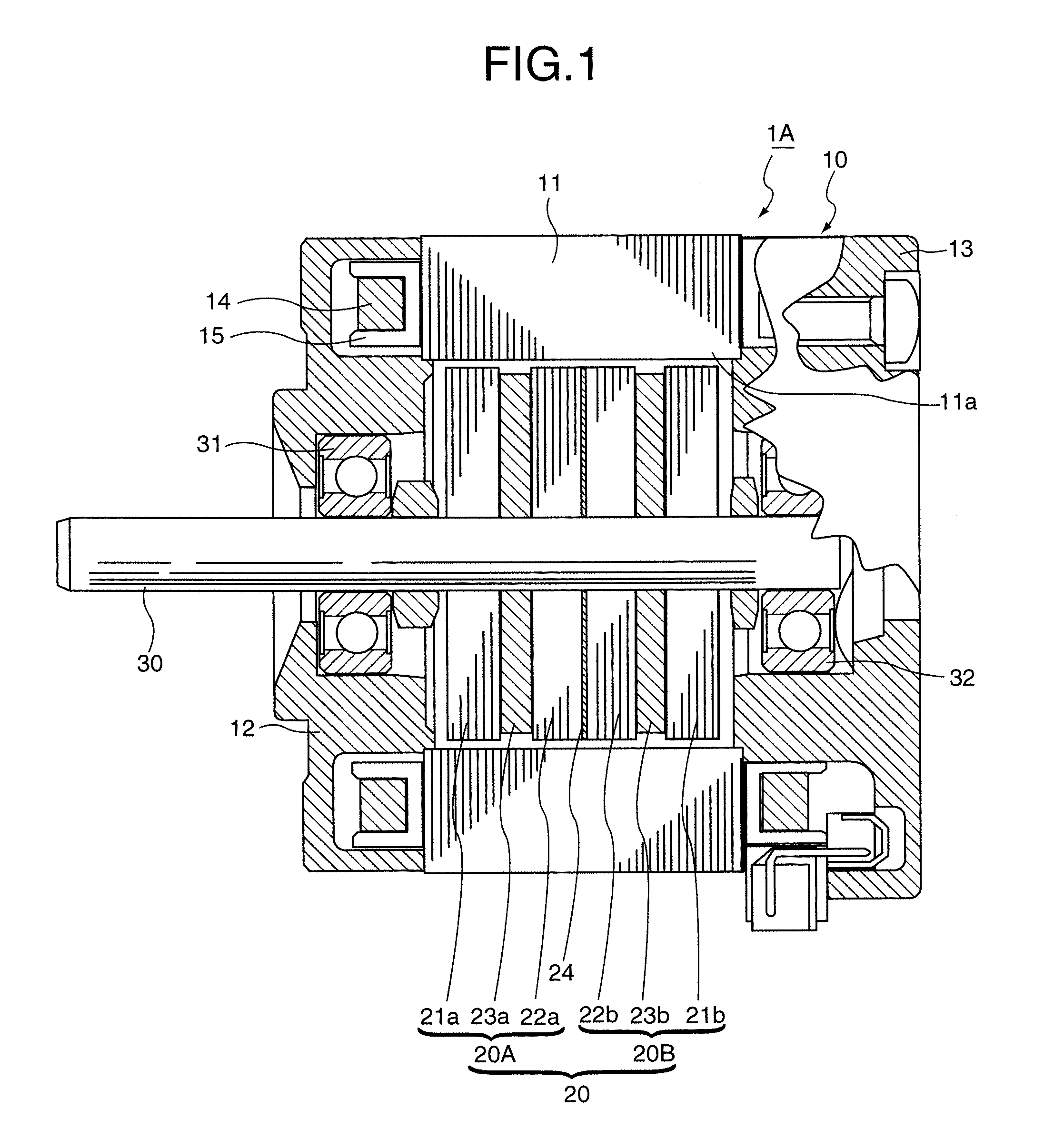
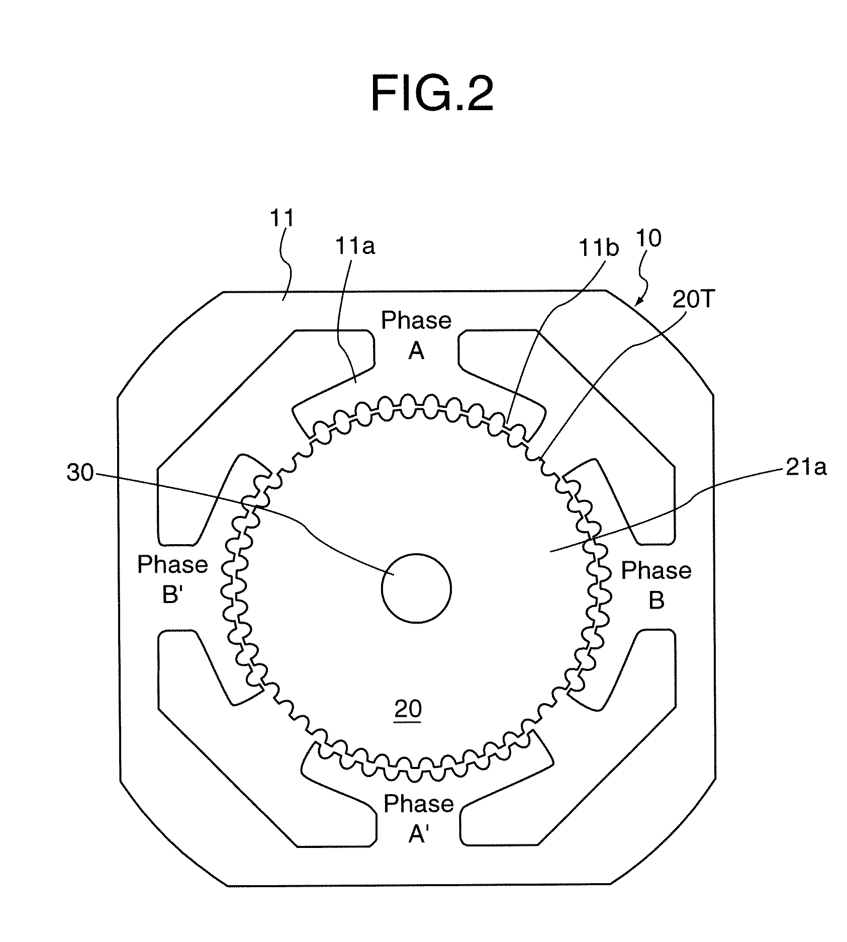
[0080]In the manufacturing method of an HB permanent magnet type electric rotating machine according to the first embodiment of the present invention, the stator 10 is constructed by winding the coils 14 around the main poles 11a of the stator core 11; the rotor 20 is constructed by fixing the first rotor unit 20A, which consists of a pair of rotor cores 21a, 22a and a magnetic material 23a (hereinafter, it is described by the reference 23a that is the same as the permanent magnet after magnetization) sandwiched between the rotor cores, and the second rotor unit 20B, which consists of a pair of rotor cores 21b, 22b and a magnetic material 23b (hereinafter, it is described by the reference 23b that is the same as the permanent magnet after magnetization) sandwiched between the rotor cores; and the rotor 20 is assembled to the stator 10 with a predetermined air gap therebetween so that the rotor 20 is free to rotate by means of the first bracket 12 arranged at the outside of the first...

second embodiment

[0093]In the manufacturing method of an HB permanent magnet type electric rotating machine according to the second embodiment of the present invention, a constructed rotor is mounted on a magnetizing device to magnetize magnet materials that constitute permanent magnets of the rotor before the rotor is assembled to a stator.

[0094]Namely, as shown in FIG. 4, the rotor 20 is constructed by fixing the first rotor unit 20A, which consists of a pair of rotor cores 21a, 22a and a magnetic material 23a sandwiched between the rotor cores, and the second rotor unit 20B, which consists of a pair of rotor cores 21b, 22b and a magnetic material 23b sandwiched between the rotor cores to the rotation shaft 30. Then, the rotor 20 is mounted on the magnetizing device 60, and the magnet materials 23a and 23b are magnetized to be permanent magnets.

[0095]The magnetizing device 60 of the second embodiment is provided with a cylindrical first yoke 61 that is arranged at one side in the axial direction, ...

third embodiment

[0106]In the manufacturing method of an HB permanent magnet type electric rotating machine according to the third embodiment of the present invention, the magnet materials are magnetized after the rotor is assembled to the stator. That is identical to the first embodiment. However, the method of the third embodiment uses a magnetizing device 70 shown in FIG. 5 instead of the magnetizing device 50 used in the first embodiment.

[0107]Namely, the stator 10 is constructed by winding the coils 14 around the main poles 11a of the stator core 11; the rotor 20 is constructed by fixing the first rotor unit 20A, which consists of a pair of rotor cores 21a, 22a and a magnetic material 23a sandwiched between the rotor cores, and the second rotor unit 20B, which consists of a pair of rotor cores 21b, 22b and a magnetic material 23b sandwiched between the rotor cores to the rotation shaft 30; and the rotor 20 is assembled to the stator 10 with a predetermined air gap therebetween so that the rotor...


PUM

PropertyMeasurementUnit
electrical angleaaaaaaaaaa
electric conductiveaaaaaaaaaa
torqueaaaaaaaaaa

Abstract

A stator is constructed by winding excitation coils around respective main poles. A rotor is constructed by fixing a first rotor unit, which consists of a pair of rotor cores and a magnetic material sandwiched between the rotor cores, and a second rotor unit, which has the same construction as the first rotor unit, to a rotation shaft. The rotor is assembled to the stator to form an assembled body. The magnet material of the first rotor unit is magnetized in the axial direction by a magnetizing flux passing through a half of the assembled body in the axial direction. The magnet material of the second rotor unit is magnetized in the axial direction in an opposite polarity by a magnetizing flux passing through the remaining half of the assembled body in the axial direction.

Description

BACKGROUND OF THE INVENTION[0001]The present invention relates to a hybrid (hereafter abbreviated as HB) permanent magnet type electric rotating machine used for OA equipment treating images, such as a facsimile, an ink-jet printer, a laser beam printer, or a copy machine. The present invention also relates to a manufacturing method of such an electric rotating machine.[0002]FIG. 14 and FIG. 15 show a conventional two-phase HB type stepping motor. FIG. 14 is a longitudinal sectional view and FIG. 15 is a front view showing a relation between a rotor core and a stator core. This stepping motor 100 is provided with a stator 110 having a stator core 111 of two-phase and eight-pole, and a rotor 130 fixed to a rotation shaft 120 that is rotatably supported inside the stator 110. The stator 110 is constructed by sandwiching a stator core 111, which is formed by stacking silicon steel plates, by a pair of brackets 112 and 113 formed from nonmagnetic material from the both sides in the axia...

Claims


Application Information

Patent Timeline
Patent Type & Authority Applications(United States)
IPC IPC(8): H02K37/14H01F1/03H01H47/00H01F1/00
CPCH02K15/03Y10T29/49012Y10T29/49009H02K37/18
Inventor SAKAMOTO, MASAFUMIKOBAYASHI, TORUAZEGAMI, MASAHIKOMOTEGI, YASUAKIKATO, TAKAYAOIWA, SHOJIMATSUDA, YASUOONISHI, KAZUOFUKUSHIMA, TADASHITANAKA, NORIMOTO
Owner NIDEC SERVO CORP
Why Eureka
Try Eureka