
Biomedical machinery and equipment clean system safety valve

A mechanical equipment, biomedical technology, applied in the direction of mechanical equipment, safety valves, valve details, etc., can solve the problems of reduced sensitivity, unsmooth movement, increased energy consumption, etc., meet high hygiene requirements, rigorous and novel design, Turn on pressure for accurate effects

Active Publication Date: 2016-02-10
ZHEJIANG HENGHUA VALVE
View PDF6 Cites 0 Cited by
  • Summary
  • Abstract
  • Description
  • Claims
  • Application Information

AI Technical Summary

Problems solved by technology

[0002] At present, the safety valves of the prior art are applied to the pipelines or pressure vessels of the protected system to ensure the safety of the pipelines or pressure vessels. However, for the cleaning system of biomedical machinery and equipment, the current safety valves have certain defects. For example, the action is not smooth enough when opening or closing, which affects the use effect; when the back pressure is changed, it is easy to affect the set pressure of the equipment, and the spare parts are easily corroded by the medium during use, which slows down the service life and increases energy consumption. It will be affected by the deflection of the spring to automatically align the center, and the sensitivity will be reduced; there is no overpressure protection device, etc.

Method used


Image

  • Biomedical machinery and equipment clean system safety valve

Examples


Embodiment Construction

[0018] The detailed description and technical content of the present invention are described below with the accompanying drawings, but the accompanying drawings are only provided for reference and description, and are not intended to limit the present invention.

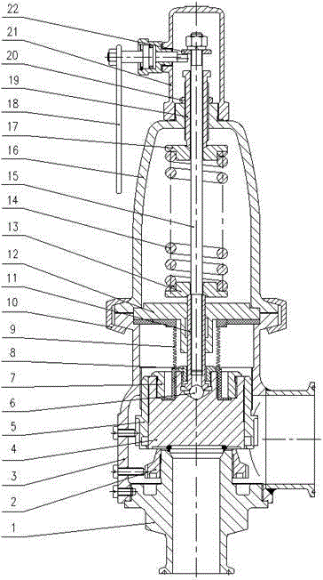
[0019] according to figure 1 As shown, the safety valve of the biomedical mechanical equipment cleaning system includes a valve body 3, a valve cover 16, and a valve stem 15, and the valve stem is arranged inside the valve cavity formed by the fastening of the valve body and the valve cover; The lower end is connected to the valve disc 4 through the guide sleeve 11, and the bottom of the valve disc 4 abuts against the top of the valve seat 1 connected with the valve body 3 at the same time; the outer circumference of the valve stem is covered with a spring 14, and the upper end of the spring passes through the The spring seat 17 abuts against the bottom of the adjusting screw sleeve 19 which is also set on the valve ...


PUM


Abstract

The invention discloses a safety valve of a cleaning system of biological medical mechanical equipment. The safety valve comprises a valve body, a valve cover and a valve rod, wherein the valve rod is arranged in a valve cavity formed by the valve body and the valve cover in a buckled mode, the lower end of the valve rod is connected to a valve flap through a guide bush, the bottom of the valve flap is connected with the top of a valve base connected with the valve body in an abutting mode, the periphery of the valve rod is provided with a spring in a sleeved mode, the upper end of the spring is connected with the bottom of an adjustment threaded sleeve arranged on the valve rod in a sleeved mode through an upper spring base in an abutting mode, the lower end of the spring is connected with the top of the guide bush arranged on the valve rod in a sleeved mode through a lower spring base in an abutting mode, the guide bush penetrates through the center of a guide sleeve and is fixed to the center of the guide sleeve, and the guide sleeve is pressed and stuck in the butt-joint position of the valve body and the valve cover in a sleeved mode. The safety valve is strict in design, has a high sanitary requirement, is good in sealing performance, and makes up for the blank of a sanitary valve of the kind in China; the opening pressure of the safety valve is accurate.

Description

technical field [0001] The invention relates to a valve, in particular to a safety valve for a cleaning system of biomedical mechanical equipment. Background technique [0002] At present, the safety valves of the prior art are applied to the pipelines or pressure vessels of the protected system to ensure the safety of the pipelines or pressure vessels. However, for the cleaning system of biomedical machinery and equipment, the current safety valves have certain defects. For example, the action is not smooth enough when opening or closing, which affects the use effect; when the back pressure is changed, it is easy to affect the set pressure of the equipment, and the spare parts are easily corroded by the medium during use, which slows down the service life and increases energy consumption. It will be automatically centered by the deflection of the spring, and the sensitivity will be reduced; there is no overpressure protection device, etc. Therefore, for places where medica...

Claims


Application Information

Patent Timeline
Patent Type & Authority Patents(China)
IPC IPC(8): F16K17/06F16K17/164
CPCF16K17/06F16K17/164F16K27/12F16K41/10
Inventor 包鑫发池岳福朱鹏飞
Owner ZHEJIANG HENGHUA VALVE
Learn More