Swallow-shaped vortex fin

A swallow-shaped and finned technology, which is applied in the field of aviation airborne equipment reliability, can solve the problems of reduced aircraft performance, high oil temperature, poor heat dissipation, etc., to improve the heat transfer efficiency of the shell, increase the heat transfer, Create a convenient effect

Inactive Publication Date: 2014-01-22
BEIHANG UNIV
View PDF6 Cites 4 Cited by
  • Summary
  • Abstract
  • Description
  • Claims
  • Application Information

AI Technical Summary

Problems solved by technology

[0002] The characteristics of high power density and poor heat dissipation of airborne equipment lead to excessively high oil temperature, which endangers flight safety. Excessively high oil temperature is an urgent problem to be solved
When the air flowing through the airborne equipment is a laminar flow, since most of the thermal resistance in the heat transfer process is concentrated on the air side, the current method of installing heat sinks to expand the heat dissipation area results in a substantial increase in the volume and weight of the equipment and reduces the performance of the aircraft
At present, most of the existing heat dissipation fins are aimed at one-sided airflow and are not suitable for arrangement on curved surfaces. In order to improve the induction and reliability of laminar air flow, the project proposes that no external power should be added, and the flow will be induced by arranging swallow-shaped vortex fins. Laminar air is turbulent, and the temperature of airborne equipment is mainly controlled by increasing the convective heat transfer coefficient rather than increasing the heat transfer area.

Method used


Image

  • Swallow-shaped vortex fin
  • Swallow-shaped vortex fin
  • Swallow-shaped vortex fin

Examples


Embodiment Construction

[0016] The present invention will be described in detail below with reference to the drawings and specific embodiments.

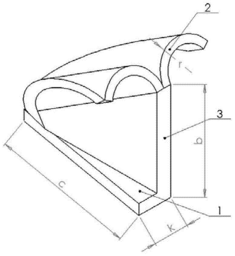
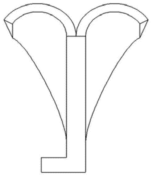
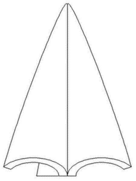
[0017] The structure of the embodiment of the present invention is as figure 1 And Figure 2 (a), Figure 2 (b), Figure 2 (c) shown. Distributed symmetrically on both sides, it is composed of a triangular base 1, a swallow-shaped wing 2 and a triangular rib 3, which are connected to each other. The triangular rib 3 is a triangular structural member, the bottom side of which is vertically connected with the triangular base 1 and the hypotenuse is connected with the bottom of the dove-shaped wing 2 and supports the dove-shaped wing 2 on the triangular base 1. The swallow-shaped wings 2 are two arc-shaped connecting pieces with a radius r, which induce laminar air into turbulent flow. The triangular base 1 is a triangular structural member, which only serves to fix the dove-shaped vortex fins. In order to reduce the quality of the fins, the size and weight of the...


PUM


Abstract

A swallow-shaped vortex fin comprises a triangular base (1), a triangular rib plate (3) and swallow-shaped wings (2) which are mutually connected. The triangular base (1) and the triangular rib plate (3) are triangular structural parts, a single side of the swallow-shaped vortex fin is fixed onto a shell of an airborne device, the bottom edge of the triangular rib plate is perpendicularly connected with the triangular base (1), the bevel edge of the triangular rib plate is connected with the bottoms of the swallow-shaped wings (2), the swallow-shaped wings (2) are supported on the triangular base (1), the triangular rib plate and the swallow-shaped wings (2) on two sides jointly induce laminar air into turbulent flow, the swallow-shaped wings (2) are two arc-shaped connectors with radiuses r, and the laminar air is induced into the turbulent flow. The swallow-shaped vortex fin is simple in structure and convenient to manufacture and has fine practical value and wide application prospect in the technical field of reliability of airborne devices, and air convection heat exchange coefficient and heat exchange amount are increased.

Description

Technical field [0001] The invention relates to a dove-shaped vortex fin, in particular to a heat exchange fin applied to airborne equipment with laminar air flowing through a casing and strict requirements on temperature, weight and reliability. It belongs to the technical field of reliability of aviation airborne equipment. Background technique [0002] The characteristics of high power density and poor heat dissipation capacity of airborne equipment lead to excessively high oil temperature, which endangers flight safety. Excessive oil temperature is an urgent problem to be solved. When the air flowing through the airborne equipment is laminar, since most of the thermal resistance in the heat transfer process is concentrated on the air side, the current method of installing heat sinks to expand the heat dissipation area has led to a substantial increase in the volume and weight of the equipment, which reduces the performance of the aircraft. At present, most of the existing he...

Claims


Application Information

Patent Timeline
Patent Type & Authority Applications(China)
IPC IPC(8): F28F3/00
Inventor 王岩张永龙
Owner BEIHANG UNIV
Why Eureka
Try Eureka