
A signal generation method for an automobile instrument detection signal generation platform

A technology for detecting signals and automotive instruments, which is applied in the field of electricity, can solve the problems of cumbersome connection and non-portability, and achieve the effect of simple interface, convenient operation, and expanded application range

Active Publication Date: 2016-01-20
HARBIN INST OF TECH
View PDF7 Cites 0 Cited by
  • Summary
  • Abstract
  • Description
  • Claims
  • Application Information

AI Technical Summary

Problems solved by technology

[0003] The purpose of the present invention is to solve the problem that several generating devices need to be used at the same time when the existing signal generating device checks all signals at the same time, and the connection is cumbersome and not portable, and provides an automobile instrument detection signal generating platform and a signal generating method thereof

Method used


Image

  • A signal generation method for an automobile instrument detection signal generation platform
  • A signal generation method for an automobile instrument detection signal generation platform

Examples


specific Embodiment approach 1

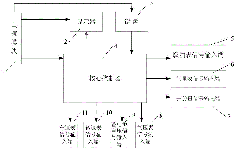
[0049] Specific implementation mode one: the following combination figure 1 Describe the present embodiment, a kind of automobile meter detection signal generation platform described in the present embodiment, it comprises power supply module 1, display 2 keyboard 3 and core controller 4;

[0050] The power supply module 1 supplies power to the core controller 4, the display 2 and the keyboard 3 respectively;

[0051] The keyboard input instruction signal output end of the keyboard 3 is connected to the core controller 4 keyboard input instruction signal input end;

[0052] The display signal output terminal of the core controller 4 is connected to the display signal input terminal of the display 2; the fuel quantity resistance signal output terminal of the core controller 4 is connected to the fuel gauge signal input terminal 5; the gas quantity resistance of the core controller 4 The signal output end is connected to the gas meter signal input end 6;

[0053] The switch si...

specific Embodiment approach 2

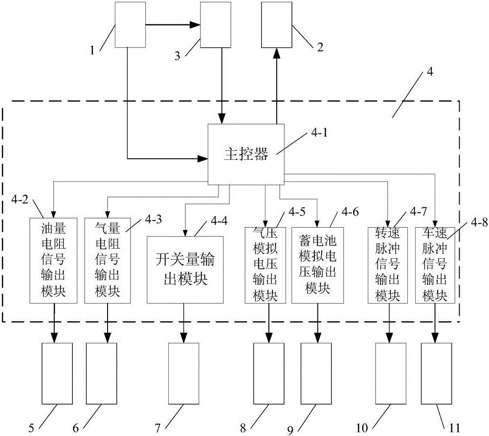
[0056] Specific implementation mode two: the following combination figure 2 This embodiment will be described. This embodiment will further explain the first embodiment. The core controller 4 in this embodiment includes a main controller 4-1, an oil resistance signal output module 4-2, and an air resistance signal output module 4-3. , switch value output module 4-4, air pressure analog voltage output module 4-5, battery analog voltage output module 4-6, speed pulse signal output module 4-7 and vehicle speed pulse signal output module 4-8;

[0057] The oil quantity resistance output control signal output terminal of the main controller 4-1 is connected to the oil quantity resistance output control signal input terminal of the resistance signal output module 4-2;

[0058] The gas volume resistance output control signal output terminal of the main controller 4-1 is connected to the gas volume resistance output control signal input terminal of the resistance signal output module 4-...

specific Embodiment approach 3

[0071] Specific implementation mode three: the following combination figure 2 This embodiment will be described. This embodiment will further describe Embodiment 2. The resistance value output by the resistance signal output terminal of the resistance signal output module 4 - 2 in this embodiment ranges from 0 to 99.999 kohm.


PUM


Abstract

The invention discloses a signal generating platform for automobile instrument detection and a signal generating method of the signal generating platform and belongs to the field of electrics. The invention aims to solve the problems that several generating devices need to be used simultaneously, and are complicated in wiring and not portable when all signals are checked simultaneously by a traditional signal generating device. A power module of the signal generating platform disclosed by the invention is used for supplying electricity for a core controller, a displayer and a keyboard; the keyboard is used for inputting a command signal to the core controller; the core controller is used for controlling the display of the displayer; the oil mass resistance signal output end of the core controller is connected with a fuel gauge signal input end; a gas quantity resistance signal output end is connected with a gas meter signal input end; a switching value signal output end is connected with a switching value signal input end; a gas pressure analog voltage signal output end is connected with a gas-pressure meter signal input end; a storage battery analog voltage output end is connected with a storage battery voltage signal input end; a revolution speed pulse signal output end is connected with a revolution meter signal input end; a vehicle speed pulse signal output end is connected with a speedometer signal input end. The signal generating platform and the signal generating method of the signal generating platform are used for the detection of automobile instrument information.

Description

technical field [0001] The invention relates to a signal generation platform of an automobile electronic control unit and a method for generating signals thereof, belonging to the field of electricity. Background technique [0002] For the finished automotive instrument, the signals processed on it include gas gauge, fuel gauge, speedometer, tachometer, barometer, etc. And these signals can be divided into resistance signal, analog voltage signal, switch signal and pulse signal according to the type. Before the meter leaves the factory, it is necessary to verify all the signals, that is, to input the corresponding resistance signal or other signals to check whether the meter has the correct indication reading. Some existing signal generators can only output some of the signals. Simultaneous inspection of all signals requires several generators to be used at the same time. The connection is cumbersome and inconvenient to use; and the application of these inspection devices i...

Claims


Application Information

Patent Timeline
Patent Type & Authority Patents(China)
IPC IPC(8): G01D18/00
Inventor 许雲淞李正超王海鹏于金泳高会军张立宪
Owner HARBIN INST OF TECH
Learn More