Position closed-loop system-based minimum phase difference tracking method
A closed-loop system and subtraction technology, applied in the direction of control using feedback, can solve problems such as insufficient performance of high-precision servo systems, and achieve the effect of obvious low-speed characteristics, improved system performance, and reduced tracking amplitude.
Inactive Publication Date: 2014-01-22
BEIHANG UNIV
View PDF3 Cites 16 Cited by
- Summary
- Abstract
- Description
- Claims
- Application Information
AI Technical Summary
Problems solved by technology
This classic control method is not enough to meet the performance requirements of high-precision servo systems, and the use of compound control methods has become the development trend of today's control systems
Method used
View moreImage
Smart ImageViewing Examples

Examples
Embodiment
[0095] In an example, the nominal model identification results are as follows Figure 6 Shown, G n (s) Each coefficient is k=50, a 0 =10,a 1 =20,b 0=5. Each coefficient of the low-pass filter Q(s) is N=3, M=1, τ=0.02. The system design bandwidth is 0.5°, 3Hz.
Login to View More PUM
 Abstract
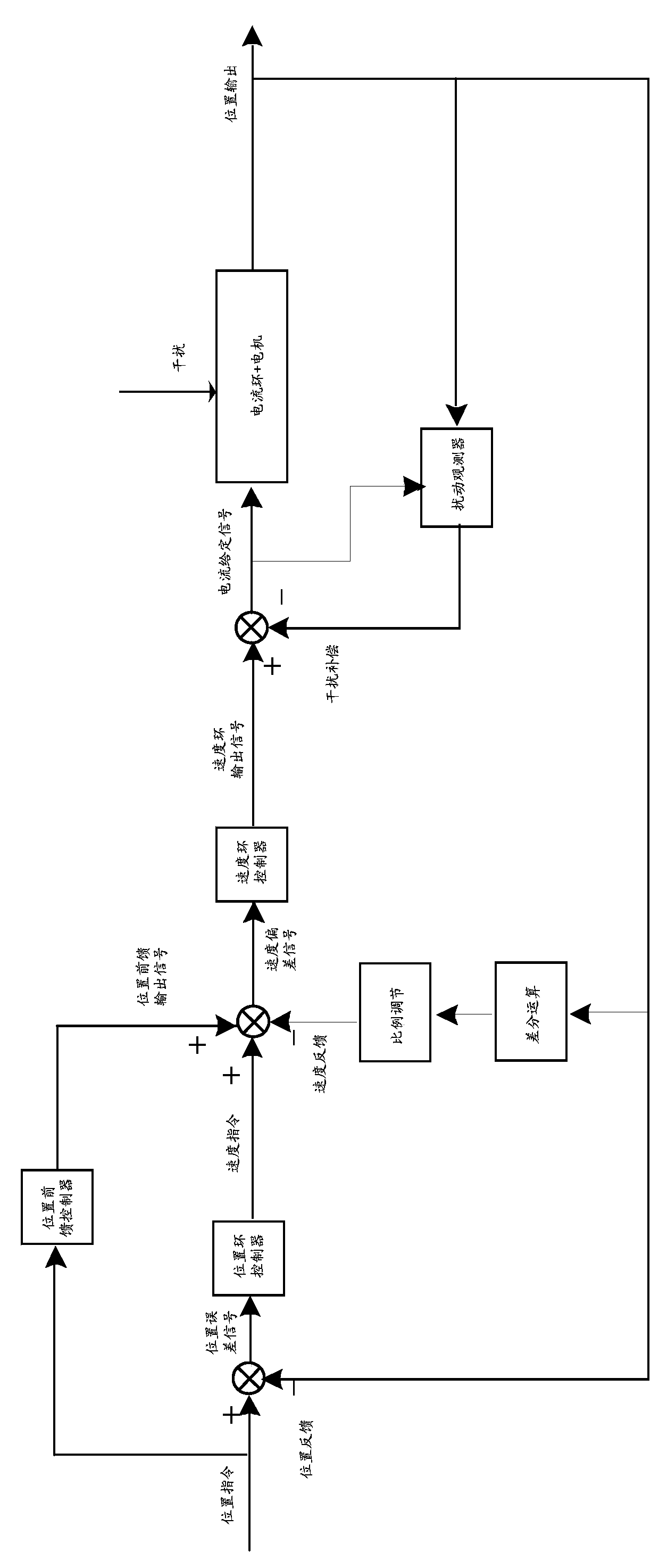
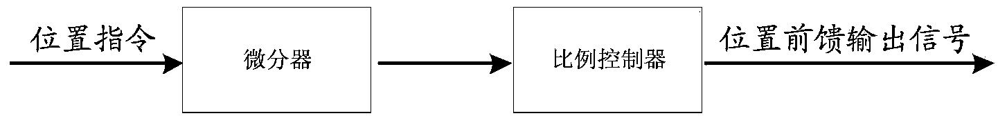
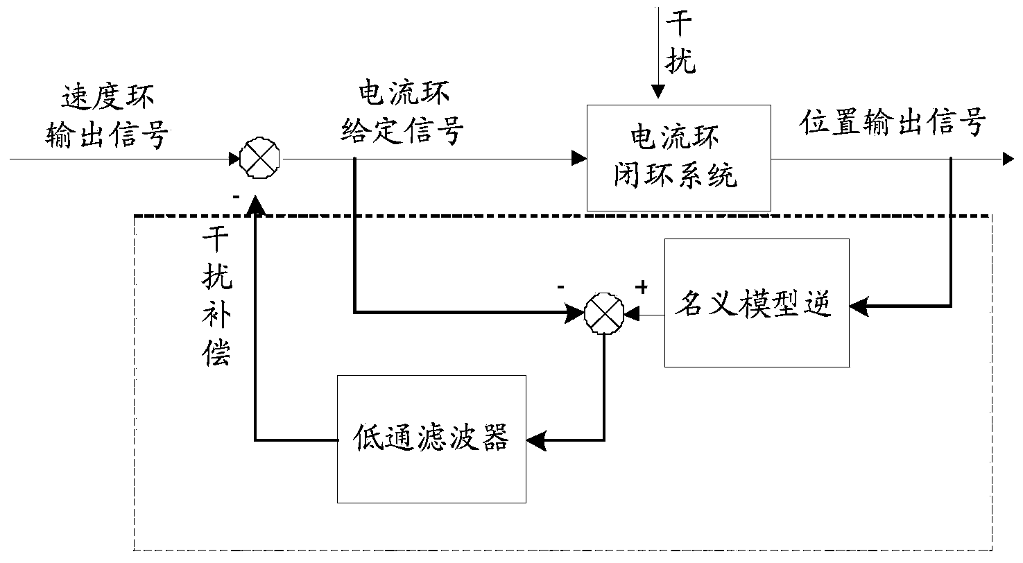
The invention discloses a novel control method, and aims to improve the tracking accuracy of a servo system. A current loop disturbance observer is constructed to effectively suppress the nonlinear disturbance of the system; a position differentiation method is used for constructing a speed closed loop on the basis of no speed measurement components to improve the rigidity (damping) of the system; a position instruction differentiation method is used for realizing first-order feed-forward and controlling the phase shift of the system; parameters of a position and speed controller are regulated to control a tracking amplitude difference; within a system index bandwidth range, double-one tracking indexes of an absolute value of a signal tracking amplitude difference of lower than 1 percent and phase lag of less than 1 degree can be achieved; particularly remarkable low-speed characteristics are achieved, and 0.00001-degree 0.024Hz distortion-free dynamic ultra-small signal tracking can be realized. The method has the characteristics of high control accuracy, wide application range, easiness for engineering practices and the like.
Description
technical field [0001] The invention relates to a servo system applied to a speed-measuring element and its minimum amplitude phase difference tracking method, which constructs a speed closed loop and increases the rigidity (damping) of the system. Background technique [0002] In recent years, with my country's outstanding achievements in aerospace, weapons development and other fields, as well as the rapid development of other industrial fields, high-precision servo systems have played a pivotal role. "High response, high precision, and ultra-low speed" are the core key elements in the development of high-precision servo systems, among which "high response" represents the ability of the servo system to track high-frequency signals; "high precision" reflects the ability of the system to track command signals Accuracy; "ultra-low speed" reflects the low-speed stability of the system. [0003] Factors affecting the performance of high-precision servo systems include many non...
Claims
Login to View More Application Information
Patent Timeline
 IPC IPC(8): G05D3/12
Inventor 扈宏杰张超
Owner BEIHANG UNIV
Features
- R&D
- Intellectual Property
- Life Sciences
- Materials
- Tech Scout
- Unparalleled Data Quality
- Higher Quality Content
- 60% Fewer Hallucinations
Learn More Browse by: Latest US Patents, China's latest patents, Technical Efficacy Thesaurus, Application Domain, Technology Topic, Popular Technical Reports.
© 2025 PatSnap. All rights reserved.Legal|Privacy policy|Modern Slavery Act Transparency Statement|Sitemap|About US| Contact US: help@patsnap.com