power conversion device

A power conversion device and power technology, applied in the direction of output power conversion device, AC power input conversion to AC power output, electrical components, etc., can solve the problems of unsatisfactory noise suppression effect and zero-phase current reduction

Active Publication Date: 2016-03-02
HITACHI LTD
View PDF11 Cites 0 Cited by
  • Summary
  • Abstract
  • Description
  • Claims
  • Application Information

AI Technical Summary

Problems solved by technology

[0008] The method of Patent Document 4 has the effect of reducing the zero-phase current, but since the switching timing of the inverter is restricted by the switching timing of the converter, the noise suppression effect is not ideal

Method used


Image

  • power conversion device
  • power conversion device
  • power conversion device

Examples


no. 1 example

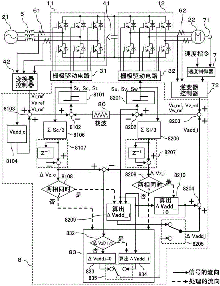
[0035] figure 1 The structure of the first embodiment of the present invention is shown. figure 1 The power conversion device can be used, for example, to drive an elevator or the like. figure 1 power conversion device, with Figure 12 As in the power conversion device shown, the AC power from the AC power source 21 is converted into DC power by the converter 11 as the conversion circuit, and the DC power smoothed by the smoothing capacitor 41 is passed through the inverter 12 (the conversion circuit) as the conversion circuit. ) into alternating current with variable voltage and frequency, and the converted alternating current is supplied to the motor 22 . In addition, in figure 1 In the example of , the DC circuit has a first potential and a second potential. In addition, the AC of the power supply 21 and the motor 22 are both multi-phase AC and three-phase AC respectively. A filter circuit 5 is connected between the power supply 21 and the inverter 11 . Each phase o...

no. 2 example

[0075] Figure 9 Shows the second embodiment of the present invention. The description of the same parts as those of the first embodiment will be omitted below, and only the different parts will be described. In the second embodiment, the carrier 801 of the converter 11 is set lower than the carrier 802 of the inverter 12 . Also in this case, the same effect as that of the first embodiment can be obtained. When the converter 11 side with a low carrier frequency corrects it based on the switching timing of the inverter 12 side, the number of switching times becomes larger than the number of switching times determined by the carrier wave 801 , which may lead to an increase in loss. Therefore, the correction voltage ΔVadd_i is superimposed only on the side of the inverter 12 with a high carrier frequency according to the switching timing of the converter 11 . In this case, the frequency of the carrier wave 802 on the side of the inverter 12 is higher than that of the first emb...

no. 3 example

[0077] Figure 10 A third embodiment of the present invention is shown. The following is only for figure 1 The different sections are explained. In the above-mentioned first and second embodiments, the superposition correction is only performed on the inverter 12 side to reduce the zero-phase current, but in this embodiment, the same correction as that on the inverter side is also performed on the converter 11 side fix. That is to say, when there are two or more switches on the side of the inverter 12 performing switching operations in the same potential change direction, if the judgment result of the judging part 8208 is positive, in the superimposed voltage calculation part 8109, the superimposed voltage The calculation section 8209 calculates the correction voltage ΔVadd_c on the converter 11 side in the same manner. This correction voltage ΔVadd_c is selected by the same selection section 8105 as the selection section 8205 . Thereafter, the correction voltage ΔVadd_c...


PUM


Abstract

The invention provides a power converting apparatus. In the power converting apparatus, unpleasant noise caused by switch action is suppressed while zero-phase current generated by switch action is decreased. The power converting apparatus comprises a DC circuit, a first converting circuit, a second converting circuit, and a controller. The DC circuit contains a first potential and a second potential. The first converting circuit is connected between a first multi-phase AC circuit and the DC circuit and performs power transformation between DC and AC with a switching element. The second converting circuit is connected between a second multi-phase AC circuit and the DC circuit and performs power transformation between DC and AC with a switching element. The controller controls the first converting circuit and the second converting circuit. The controller performs control in order that when more than two phases of the first converting circuit are simultaneously converted from the first potential to the second potential, at least one phase of the second converting circuit is converted from the first potential to the second potential.

Description

technical field [0001] The present invention relates to a power conversion device composed of switching elements, in particular to a technology for controlling the power conversion device composed of a PWM rectifier and a PWM inverter. Background technique [0002] Figure 12 This is an example of the configuration of the power conversion device. In variable speed drives of electric motors, such as Figure 12 As shown, the general method is to convert the AC power source 21 into DC through the converter 11, convert the DC power smoothed by the smoothing capacitor 41 into the AC with variable frequency and voltage through the inverter 12, and convert the obtained Alternating current is supplied to the motor 22 to drive it. Each phase of the converter 11 and the inverter 12 is composed of a pair of upper and lower switching elements (here, an IGBT (Insulated Gate Bipolar Transistor) will be used as an example), and the upper and lower switching elements are alternately switch...

Claims


Application Information

Patent Timeline
Patent Type & Authority Patents(China)
IPC IPC(8): H02M5/458H02M1/44H02M1/08
Inventor 森和久迫田友治保立尚史薮内达志大沼直人
Owner HITACHI LTD
Why Eureka
Try Eureka