Dual-heating laminated board

A double heating and laminated board technology, applied in the direction of ohmic resistance heating, electric heating devices, electrical components, etc., can solve the problems of fast heating wire rise speed, maximum temperature fluctuation, uneven heat transfer, etc., to improve work efficiency and meet the maximum High temperature requirement, energy saving effect

Active Publication Date: 2014-01-22
GUANGDONG SHENGYI SCI TECH
View PDF3 Cites 0 Cited by
  • Summary
  • Abstract
  • Description
  • Claims
  • Application Information

AI Technical Summary

Problems solved by technology

[0004] At present, the heating laminates of laminating machines appearing on the market generally use electric heating, as shown in Figure 1, this electric heating method is to lay electric heating wires ( Not shown in the figure), specifically, a number of receiving holes 21` parallel to each other are set at equal intervals in the central position of the plate body, and the heating wire is correspondingly installed in the receiving hole 21`, and the heating wire is energized and generates heat, so that the laminated board is heated The temperature reaches the set temperature; however, this electric heating method has the defect of uneven heat transfer to the heating laminate due to the laying of the electric heating wire at a little interval, which makes the temperature difference at different distances from the electric heating wire larger. The heating wire rises fast, so the formation of this temperature difference is increased, making the uneven heat transfer more obvious, and making the heated laminate unable to maintain the highest temperature for a long time, resulting in relatively large fluctuations in the highest temperature, which affects the quality of the product

Method used


Image

  • Dual-heating laminated board
  • Dual-heating laminated board
  • Dual-heating laminated board

Examples


Embodiment Construction

[0020] Embodiments of the present invention will now be described with reference to the drawings, in which like reference numerals represent like elements.

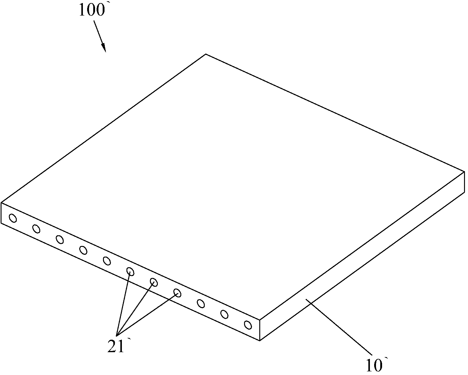
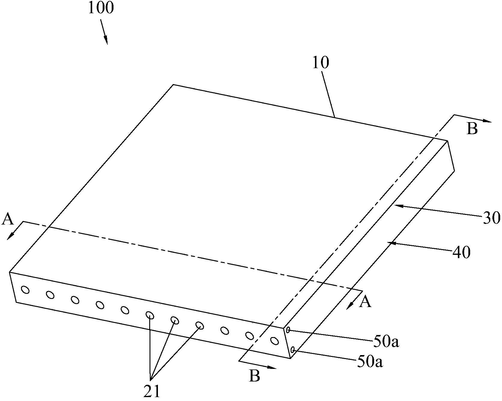
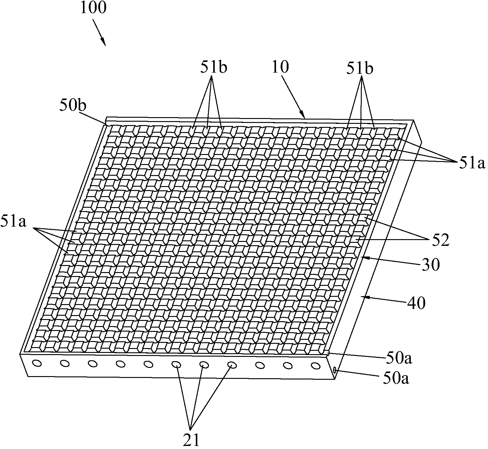
[0021] Such as Figure 2-Figure 6 As shown, the dual heating laminate 100 of the present invention includes a board body 10 and heating wires (not shown in the figure), the heating wires are uniformly arranged in the board body and form an electric heating layer 20, specifically, the The central position of the plate body 10 is provided with a number of parallel receiving holes 21 at equal intervals, and the heating wires are correspondingly installed in the receiving holes 21. The upper end 30 and the lower end 40 of the plate body 10 are provided with a number of equally spaced and staggered fluid channels. 51, interlaced fluid channels 51 form a grid-like fluid heating layer 50; The fluid heating layer 50 at the lower end 40 is symmetrically located on both sides of the electric heating layer 20 . Continue to combine...


PUM


Abstract

The invention discloses a dual-heating laminated board, which comprises a board body and electric heating wires, wherein the electric heating wires are arranged in the board body, and form an electric heating layer; a plurality of fluid passages are formed at an equal interval in each of the upper and lower ends of the board body in a staggered way; the staggered fluid passages form latticed fluid heating layers which are communicated with external high-temperature fluid; the fluid heating layers at the upper and lower ends of the board body are symmetrically positioned on the two sides of the electric heating layer. According to the dual-heating laminated board, the fluid heating layers for performing heating through the fluid are additionally arranged on the basis of electric heating, the fluid can be rapidly and uniformly injected into the fluid heating layers, and the heat of the fluid can be rapidly, uniformly and continuously transferred to the board body by combining a latticed design, so that the dual-heating laminated board can be uniformly and rapidly heated to specified highest temperature, and can be kept at the highest temperature for a long time; moreover, a plurality of heating modes can be selected according to actual needs, and meanwhile, the dual-heating laminated board also has a rapid cooling function.

Description

technical field [0001] The invention relates to a lamination equipment for PCB boards, in particular to a heating lamination board of the lamination equipment. Background technique [0002] Printed circuit board (English: Printed circuit board; abbreviation: PCB board), PCB board is divided according to the number of layers, which can be divided into three categories: single-sided PCB board, double-sided PCB board and multi-layer PCB board. [0003] PCB board is generally composed of copper foil, resin, inner layer and other components, and it needs to be manufactured by heating, pressurizing and other processes during manufacturing. At present, the PCB board has become an indispensable main component for most electronic products to achieve circuit interconnection. With the rapid increase of circuit signal transmission speed and the wide application of high-frequency circuits, higher requirements are also put forward for PCB boards. Among them, the laminator is one of the ...

Claims


Application Information

Patent Timeline
Patent Type & Authority Applications(China)
IPC IPC(8): H05K3/00H05B3/28
Inventor 蔡成菁孙慧远
Owner GUANGDONG SHENGYI SCI TECH
Why Eureka
Try Eureka