Carpet cleaning machine

A technology for carpet cleaners and rear fuselages, applied to carpet cleaners and machine components, which can solve the problems of low correlation of function realization, uneasy and reasonable operation process, and high cost, so as to achieve reasonable function distribution, strong integrity, Easy to use effects

Active Publication Date: 2014-01-29
TECHTRONIC CORDLESS GP
View PDF7 Cites 7 Cited by
  • Summary
  • Abstract
  • Description
  • Claims
  • Application Information

AI Technical Summary

Problems solved by technology

The disadvantage of this application is that the operation process is not simple and reasonable enough, and the low correlation of function realization leads to high cost

Method used


Image

  • Carpet cleaning machine
  • Carpet cleaning machine
  • Carpet cleaning machine

Examples


Embodiment 1

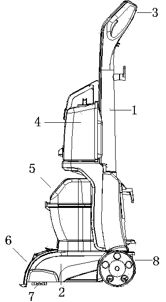
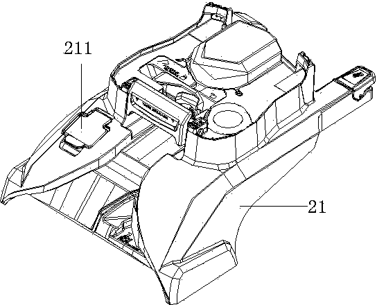
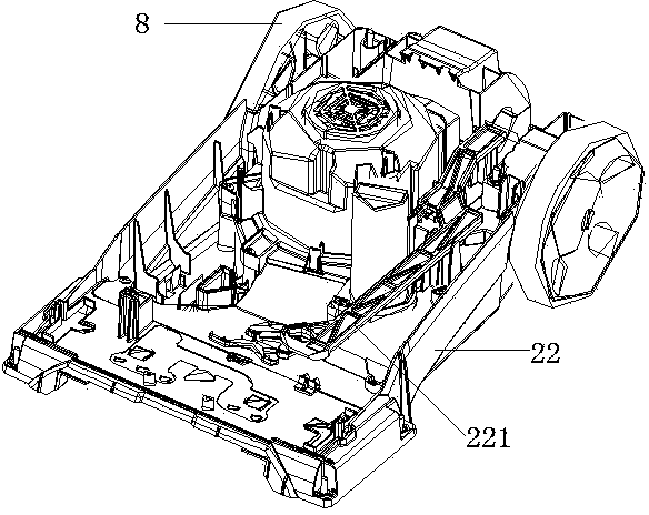
[0030] Embodiment 1: as figure 1 , figure 2 , image 3 , Figure 4 , Figure 8A kind of carpet cleaning machine shown, comprises the rear fuselage 1 with runner 8, mop base 2, described rear fuselage 1 rear upper end is provided with operating handle 3, and described rear fuselage 1 is provided with There are a solution barrel 4 and a recovery barrel 5. The mop seat 2 is provided with a motor, and the motor pumps air to form a negative pressure source chamber in the mop seat 2. The solution barrel 4 is connected to a turbo pump. The floor mop seat 2 is also provided with a sewage suction nozzle 6 and a discharge brush 7, the discharge brush 7 is powered by a transmission pump, the sewage suction nozzle 6 communicates with the recovery bucket 5, and the recovery bucket 5 is provided with There is an air outlet pipe 523 communicating with the negative pressure source cavity, and the negative pressure source cavity communicates with the air passage in the turbo pump and the ...

Embodiment 2

[0031] Embodiment 2: The structure and implementation of this embodiment are basically the same as in Embodiment 1, the difference is that it has such Figure 5 , Figure 6 Recycle Bin 5 as shown, as in Figure 7 As shown in the water storage device 9, the recovery barrel 5 includes an upper body 51 and a lower body 52, a separation plate 53 is provided between the upper body 51 and the lower body 52, and the lower body 52 is provided with Air inlet 521, described separation plate 53 is provided with airway hole, floating stop hole 531, inner air outlet hole 532, air outlet hole 533, and described lower body 52 is provided with the air inlet that links to each other with air inlet 521 The air inlet 522 is connected to the upper body 51 through the air passage hole, the air inlet 522 is connected to the inner air outlet 532, and the lower end of the separation plate 53 is provided with a floating check valve 534 with air holes. The float spool 535 of the floating stop valve 5...


PUM


Abstract

The invention discloses a carpet cleaning machine which overcomes the shortcomings that in the prior art, the carpet cleaning machine is poor in integral operation convenience, efficiency, reasonable structure and integration degree of functions. The carpet cleaning machine comprises a rear machine body with rotary wheels and a floor mapping seat, wherein an operation handle is arranged at the upper end of the rear portion of the rear machine body; a solution barrel and a recovery barrel are arranged on the rear machine body; a motor is arranged on the floor mapping seat and sucks air to form a negative pressure source chamber in the floor mapping seat; the solution barrel is connected with a turbine pump; a sewage suction nozzle and a discharge brush are arranged on the floor mapping seat; power is supplied to the discharge brush by a transmission pump; the sewage suction nozzle is connected with the recovery barrel; an air outlet pipe communicated with the negative pressure source chamber is arranged on the recovery barrel; and the negative pressure source chamber is communicated with an air channel in the turbine pump and an air channel in the transmission pump. The carpet cleaning machine is suitable for occasions needing carpet cleaning and has the advantages of being strong in integrality, reasonable in function allocation, good in operability, stable in work process and the like.

Description

[0001] technical field [0002] The invention belongs to the field of cleaning appliances, in particular to a carpet cleaning machine. [0003] Background technique [0004] As a cleaning tool, the carpet cleaning machine has been widely used in families, hotels, etc. The main functions of the carpet cleaning machine are cleaning, brushing, and recycling. Correspondingly, the carpet cleaning machine should also have water supply components, floor brush components and sewage recovery components. These components have different functions but are closely related. The carpet cleaning machines of the prior art have no obstacles in the simple realization of functions such as cleaning, floor brushing, and recycling, but there are still some shortcomings in the convenience and effectiveness of the overall operation, the rationality of the structure, and the degree of integration of functions. lacking. [0005] See the "carpet cleaning machine" disclosed in the Chinese patent lite...

Claims


Application Information

Patent Timeline
Patent Type & Authority Applications(China)
IPC IPC(8): A47L11/32A47L11/40
Inventor 张罗欢
Owner TECHTRONIC CORDLESS GP
Why Eureka
Try Eureka