
Punching and cutting die for end portion of wire collecting pipe

A tube end and punching die technology, applied in the field of terminal and controller matching processing device, can solve the problems that the quality of crimping cannot be guaranteed, the reliability cannot be guaranteed, and the production efficiency is low, so as to change the chaotic situation, resist the Guaranteed tensile strength and high production efficiency

Inactive Publication Date: 2014-01-29
TIANJIN DESHENGYUAN ELECTRONICS
View PDF0 Cites 0 Cited by
  • Summary
  • Abstract
  • Description
  • Claims
  • Application Information

AI Technical Summary

Problems solved by technology

[0002] In the existing electronics industry, the terminals of the connectors are connected to the controller, and after the wires are covered with a collecting tube, manual pliers are used to reinforce them. Because the manual pliers not only cannot guarantee the reliability of crimping, but also have low production efficiency, The quality of the crimping cannot guarantee the use requirements, and the phenomenon of shedding often occurs, causing the failure of the whole machine, especially in the case of high current, which brings great losses to customers.

Method used


Image

  • Punching and cutting die for end portion of wire collecting pipe
  • Punching and cutting die for end portion of wire collecting pipe

Examples


Embodiment Construction

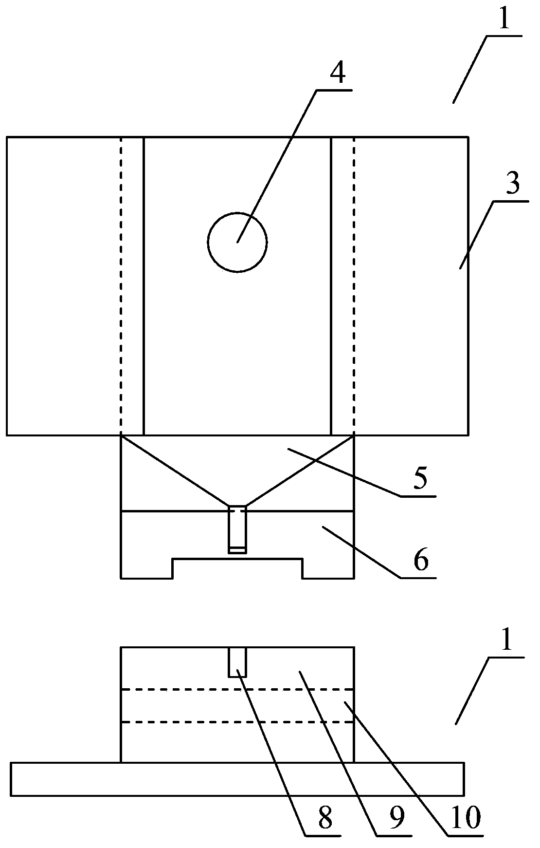
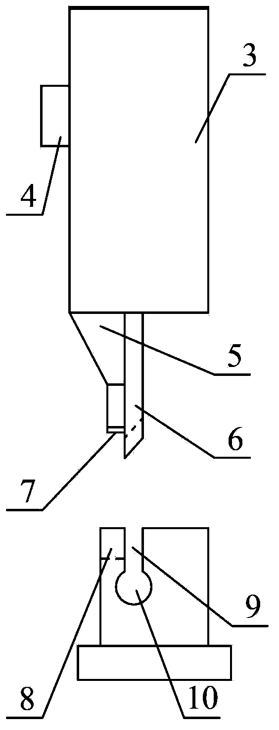
[0016] Such as figure 1 with figure 2 As shown, the present invention includes an upper die 1 and a lower die 2, and the upper die 1 includes a mounting part 3 and a punching die 5 and a cutting die 6 installed on the mounting part 3 by bolts 4, and the punching die 5 is located in the Cutting die 6 outside, and the center line of described punching die 5 and described cutting die 6 is on the same vertical plane, described punching die 5 lower end surface is provided with the bar-shaped protrusion 7 parallel with described punching die 5, so The position of the lower die 2 corresponding to the die 5 is provided with a vertical groove 8 , and the position corresponding to the cutting die 6 is provided with a horizontal groove 9 .

[0017] The lower end of the horizontal groove 9 is provided with a cylindrical through groove 10 .

[0018] An embodiment of the present invention has been described in detail above, but the content described is only a preferred embodiment of the ...


PUM


Abstract

The invention provides a punching and cutting die for the end portion of a wire collecting pipe. The punching and cutting die comprises an upper die and a lower die. The upper die comprises an installing part, a punching die and a cutting die, wherein the punching die and the cutting die are installed on the installing part through bolts, the punching die is located outside the cutting die, the center line of the punching die and the center line of the cutting die are located on the same vertical surface, a bar-shaped protrusion parallel to the punching die is arranged on the surface of the lower end of the punching die body, a vertical groove is formed in the position, corresponding to the punching die, of the lower die, and a horizontal groove is formed in the position, corresponding to the cutting die, of the lower die. The punching and cutting die has the advantages that production efficiency is high and pressing connecting quality can certainly meet quality standards.

Description

technical field [0001] The invention relates to the field of matching processing devices for terminals and controllers in the electronic industry, in particular to a punching and splitting die for the end of a wire-collecting pipe. Background technique [0002] In the existing electronics industry, the terminals of the connectors are connected to the controller, and after the wires are covered with a collecting tube, manual pliers are used to reinforce them. Because the manual pliers not only cannot guarantee the reliability of crimping, but also have low production efficiency, The quality of the crimping cannot guarantee the use requirements, and the phenomenon of shedding often occurs and causes the failure of the whole machine, especially in the case of a large current, which brings great losses to the customer. Contents of the invention [0003] The purpose of the present invention is to overcome the above problems and provide a punching and splitting die for the end o...

Claims


Application Information

Patent Timeline
IPC IPC(8): B21D37/10
Inventor 李智成张彦铭
Owner TIANJIN DESHENGYUAN ELECTRONICS
Learn More