
Motor vehicle with height adjusting device for loading floor

A technology for motor vehicles and floor plates, applied in vehicle parts, transportation and packaging, etc., can solve problems such as laborious pulling and pressing

Active Publication Date: 2014-01-29
GM GLOBAL TECH OPERATIONS LLC
View PDF5 Cites 5 Cited by
  • Summary
  • Abstract
  • Description
  • Claims
  • Application Information

AI Technical Summary

Problems solved by technology

In order to move the load floor with the height adjustment device from the lower load floor position to the upper load floor position, laborious pulling and pressing is therefore required on the rear end area of ​​the load floor

Method used


Image

  • Motor vehicle with height adjusting device for loading floor
  • Motor vehicle with height adjusting device for loading floor
  • Motor vehicle with height adjusting device for loading floor

Examples


Embodiment Construction

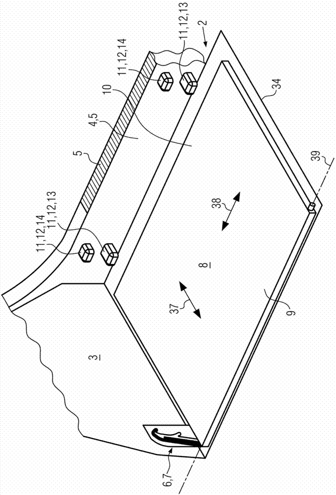
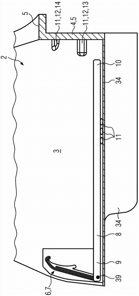
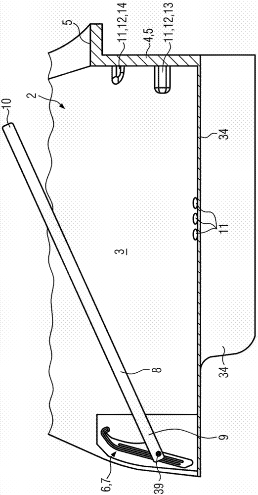
[0039] exist Figure 10 The motor vehicle 1 shown in FIG. 1 has an internal combustion engine and / or an electric motor for driving the motor vehicle. Two front seats and three rear seats are provided in the interior of the motor vehicle 1 . This is a five-door motor vehicle 1 with four side doors for getting on and off passengers and a cargo compartment 2 ( figure 1 ) for loading and unloading the rear fifth door as a tailgate. Here, the load compartment 2 is delimited rearwardly by a rear body wall 4 and an interior trim panel on the rear body wall 4 as loading edge 5 , and laterally by two body side walls 3 and an inner trim on the body side walls 3 . The plaque defines the border. Forwards, the cargo space 2 is bounded by the backrests of the three rear seats (not shown). The cargo space 2 is bounded downwards by a plate-like and substantially rectangular cargo floor 8 made of metal and / or plastic. In this case, the cargo floor 8 is oriented substantially horizontally ...


PUM


Abstract

A motor vehicle includes, but is not limited to a loading floor, a height adjusting device for the loading floor with a guide, on which the loading floor is mounted pivotably on a front end portion about a pivot axis and movably for a movement with a component in vertical direction and the loading floor with the guide can be mounted in at least two different height positions, at least two support elements formed in a different vertical orientation for supporting a rear end portion of the loading floor in the at least two different height positions. The guide includes, but is not limited to a first guideway for moving the front end portion towards the top and a second guideway for moving the front end portion towards the bottom and the first and second guideway are formed spatially separated on the guide.

Description

technical field [0001] The invention relates to a motor vehicle. Background technique [0002] A motor vehicle having an internal combustion engine and / or an electric motor for driving the motor vehicle and vehicle seats for accommodating passengers in a passenger space for transporting passengers. In this case, motor vehicles of this type usually also have a cargo compartment for accommodating objects or luggage. In this case, the cargo compartment is delimited below by the cargo floor, and generally on the sides by body side walls and trim panels on the body side walls, behind it by the body rear wall and the trim panels of the body rear wall and as the body rear wall The loading edge of defines the boundary. The cargo compartment is usually arranged behind the rear seats or rear seat backrests, ie the cargo compartment is bounded forwards by the rear seats. In this case, the rear seat backrests are generally pivotable about a pivot axis oriented in the transverse direc...

Claims


Application Information

Patent Timeline
Patent Type & Authority Applications(China)
IPC IPC(8): B60R5/04
CPCB60R5/045B60R5/04
Inventor D.德马
Owner GM GLOBAL TECH OPERATIONS LLC
Learn More