Cathode arc target cooling device

A cathodic arc target and cooling device technology, applied in the field of heat dissipation equipment, can solve the problems of large quantity restriction, troublesome replacement of target materials, affecting production efficiency and the like

Inactive Publication Date: 2015-09-30
YICHANG HOUHUANG VACUUM TECH
View PDF0 Cites 5 Cited by
  • Summary
  • Abstract
  • Description
  • Claims
  • Application Information

AI Technical Summary

Problems solved by technology

However, due to the small volume and large quantity of the small arc target itself, the improvement of production efficiency is restricted.
[0003] In the production process, as the target material is consumed, the target material needs to be replaced frequently, such as figure 1 As shown, when designing the cathode target base 1, an interlayer 4 is left between the target material 2 (cathode) and the cooling water channel 3 to realize the sealing of the vacuum cavity and block the water channel, preventing cooling from entering the vacuum cavity. This method is convenient to replace the target material, but it has a fatal weakness that the cooling effect is not good, and the particles of the coating layer are large, which greatly limits the application of cathodic arc ion plating technology on the surface of more precise tools.
[0004] like figure 2 It is an improved cathode arc target cooling method. There is no interlayer between the target 2 (cathode) and the target base 1. The cooling water directly cools the cathode target through the water channel 3. The cooling effect is good, but in order to seal it needs to be sealed in the target There is a sealing ring between the base and the base, and the target must be fixed firmly. If cooling water enters the vacuum chamber accidentally, it will seriously affect the vacuum and greatly reduce the coating quality. At the same time, it will also bring great trouble to the replacement of the target. In addition, the number of small arc targets on the vacuum chamber ranges from a few to dozens, which further increases the complexity of the work and affects the improvement of production efficiency.

Method used


Image

  • Cathode arc target cooling device
  • Cathode arc target cooling device
  • Cathode arc target cooling device

Examples


Embodiment Construction

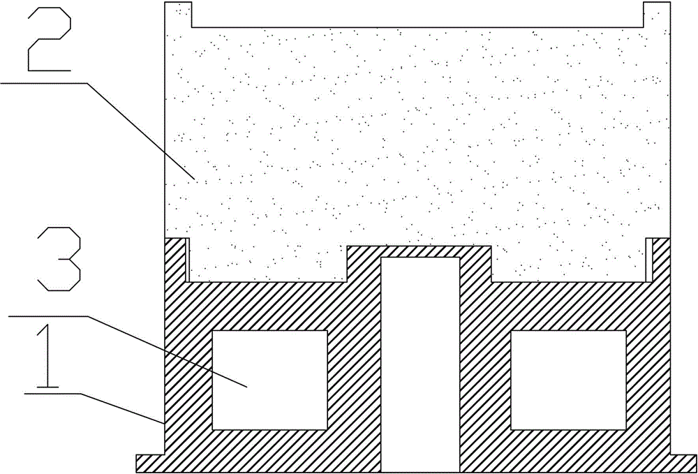
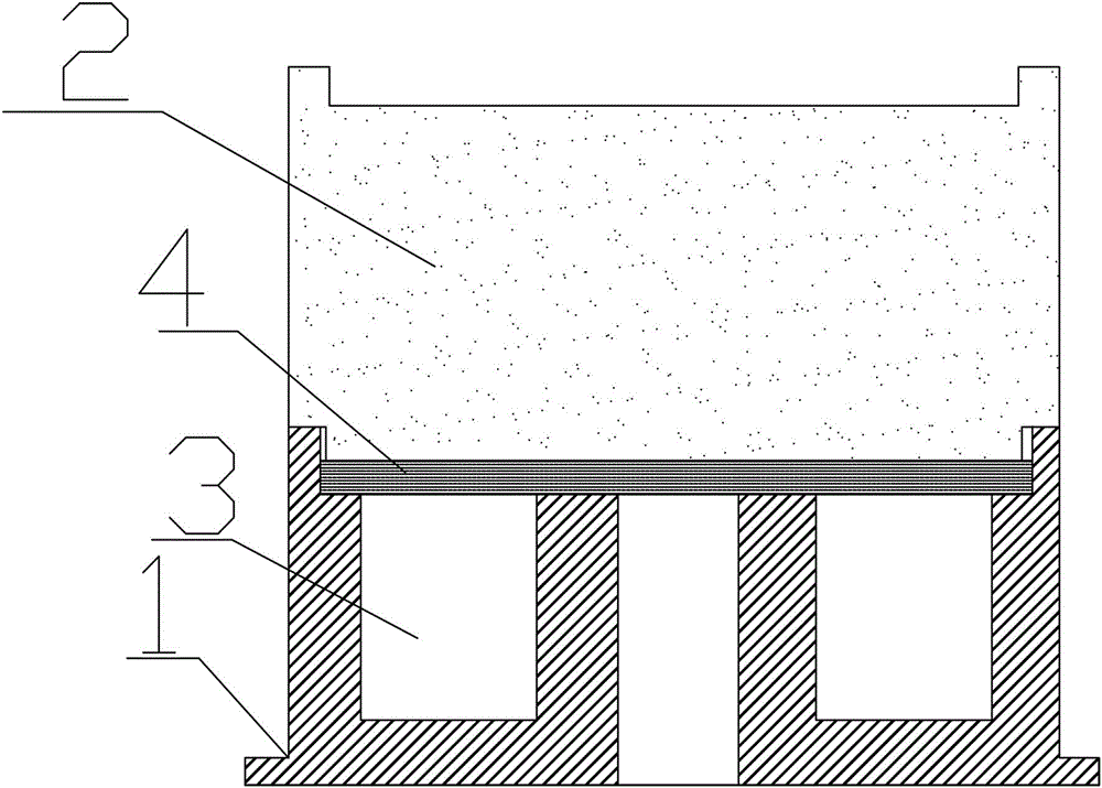
[0021] Such as image 3 Among them, a cathode arc target cooling device includes a target base 1, a target material 2, and two side-by-side cooling water channels 3 arranged inside the target base 1, the target material 2 is embedded on the surface of the target base 1, and the thickness of the copper plate 4 is 0.5 -2mm;

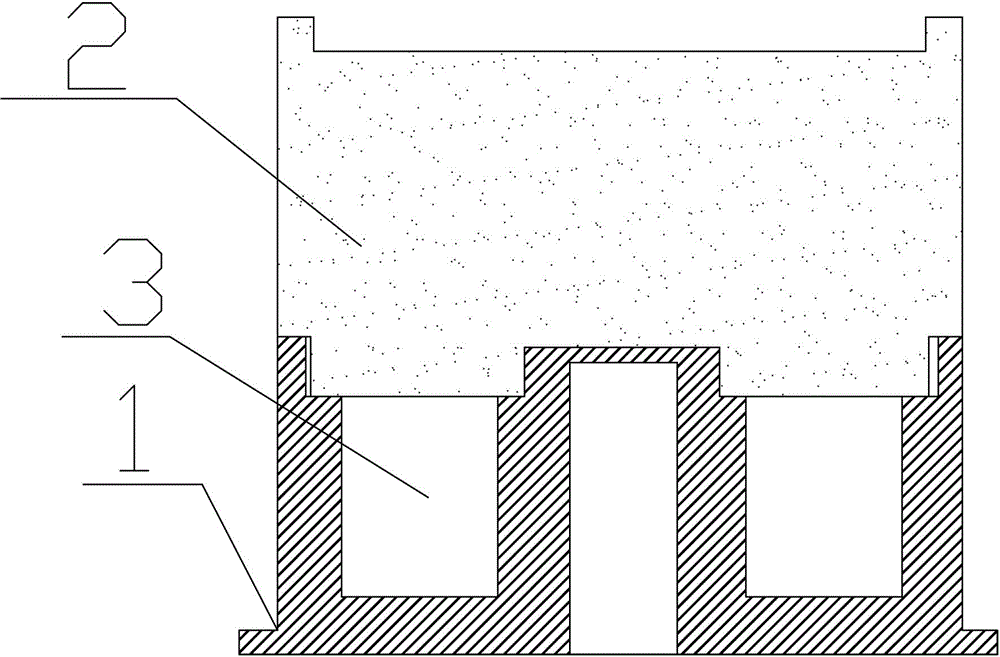
[0022] The target material 2 and the cooling channel 3 are separated by a copper plate 4. The copper plate 4 makes the cooling channel 3 and the target material 2 belong to different independent spaces. The strength temperature-resistant glue bonds the edge of the copper plate 4 on the top of the target base 2 ( image 3 , Figure 4 The middle is glued on the step of the target base 2) or the edge of the copper plate 4 is fixed in the target base 2 by one-time casting method, and the target material 2 is in contact with the copper plate 4;

[0023] Such as Figure 4 , when the liquid (cooling water) passes through the cooling channel 3, the copper plate...


PUM


Abstract

The invention discloses a cathode arc target cooling device which comprises target bases, targets and a plurality of cooling water channels formed inside the target bases, wherein the targets are embedded in the surfaces of the target bases and are isolated from the cooling water channels by using copper plates; the copper plates divide the cooling water channels and the targets into different independent spaces; the targets contact the copper plates; when a liquid flows through the water cooling channels, the copper plates protrude out towards the targets under the pressure of the liquid. The cathode arc target cooling device has the advantages that as good conductivity of copper pieces is adopted to conduct heat, and meanwhile the targets are isolated from the cooling water channels by using the copper pieces, the equipment is good in cooling effect, and in addition, vacuum equipment and production efficiency are not affected.

Description

technical field [0001] The invention relates to a cooling device, in particular to a cathode arc target cooling device. Background technique [0002] With the continuous improvement of human living standards and the continuous development of science and technology, people have put forward higher and higher requirements for the living environment. Protecting the environment and saving energy materials have become the goals that people are tirelessly pursuing in today's society. Tool surface coating technology, coating a layer of high-performance film material on the surface of the tool can greatly improve the performance and service life of the tool, which undoubtedly saves materials and reduces costs, but the initial tool surface coating technology, such as electroplating, Technologies such as spraying, either have too high environmental costs, or have limited improvement in tool performance, which not only endangers the environment, but also has a limited degree of saving m...

Claims


Application Information

Patent Timeline
Patent Type & Authority Applications(China)
IPC IPC(8): C23C14/32
Inventor 田灿鑫韩滨付德君
Owner YICHANG HOUHUANG VACUUM TECH
Why Eureka
Try Eureka